 |
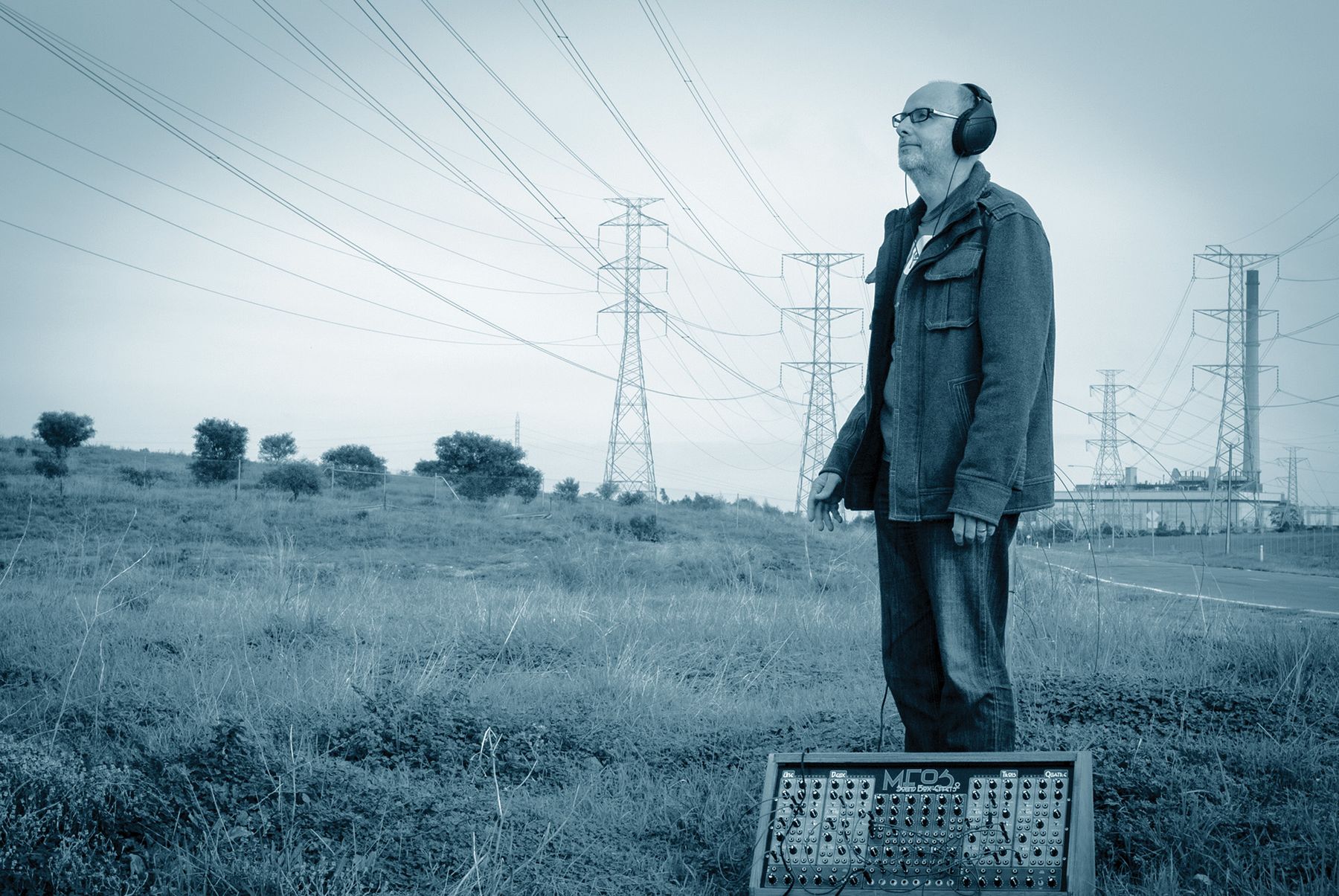
| This shows the Waveform Sequencer at Top Left, Meter Box at Top Right, The Expanse in the Middle and at the Bottom is the Sound Box Effets. |
The Expanse is a new part of my "modular" synthesizer setup in, what I call, the Analogue Department.
My most used noise machine is the SBE2 - Sound Box Effets 2 which I made back in 2013. No, that's not a spelling mistake, it is French for effects. This contains two of Music From Outer Space's Experimenters boards along with a pile of smaller modules which include Sample and Holds and a couple of SVF modules.
The SBE2 has four main modules which are all the same. They contain an oscillator, Low Pass Filter, Low Frequency Oscillator, Voltage Controlled Amplifier , an Attack Release generator and two attenuators. These are named Une, Deux, Trois and Quatre which is continuing the French theme. In addition, in the middle, are two PAIA State Variable Filters, two MFOS Sample and Holds, two mixers and six attenuators. Along the bottom of the unit are two more larger mixers and banana to 1/4" socket converters.
This is a great unit for effects but I wanted more of course. The SBE2, as mentioned, is great for effects but when it comes to more chromatic options, I didn't have any VCO's of note plus the modules are very basic. So, the design of the Expanse began.
The Expanse is a combination of existing module designs from a few different source - Music From Outer Space, YuSynth, Baton Musical Circuits and a few of my own designs. There are duplicates of each module in all but a few cases.
Here's a list of the modules:-

PRSA and B - these are pressure sensors to voltage converters. Two resistive pads are mounted on the left hand side of the Expanse. The modules will take that pressure and output a control voltage in my standard modulator voltage range which is -5 to +5v, based on the pressure. There are two controls which set the upper and lower voltages and another control which is a voltage lag control. A switch controls a voltage hold whereby you turn it on while holding a voltage with the resistive pad and the voltage will stay there. There are four outputs. Two outputs are the control voltage but one is inverted. Two outputs are the Trigger / Gate with one also being inverted. There's a switch which changes between the output trigger being a trigger or a gate. A LED indicates the status of the Trigger / Gate.
The unit is my design using a Arduino Pro Mini which takes the two analogue inputs via some analogue circuitry and the Arduino creates the -5 to +5v voltage output. It use a dual channel digital to analogue converter in the form of a MCP4922 which is a dual 12 bit converter. It's a little overkill but I had a stock of these to use. After the DAC we have a op amps to converter the voltage range back to -5 to 5v.
LAG-A and B - these are two LAG processors. A LAG processor takes a control voltage input and slow it's change down. Sort of filter. This design comes from Scott Juskiw's modified version of Harry Bissell's Morph Lag design. We have two controls which change the Attack and Decay time of the lag along with a switch to change between a linear and log LAG response curve. There's a simple input and output. The input voltage will be clamped from -5 to +5v.
SSM VCA A and B - These are on one board and are the same VCA boards as used in my FloriVoxTron. It uses a V2164 which is the Alfa modern version of the classic SSM 2164 voltage controlled amplifier. It's a pretty straight forward design coming from Mark Irwin. I've set these up with the idea that we use a separate audio mixer before them hence they only have one audio input but two control voltage inputs, one has an attenuator. There's also an INIT control applies a control voltage to the VCA to open it up.
During MIDI mode, we still have one random pulse output with an associate control for the maximum time but an added feature is that one of the trigger inputs now controls the state of the random output. Since it's MIDI mode, we have another trigger output which has MIDI CLOCK On it with another control which affects a divisor on this clock. The two control voltage outputs and the other two trigger outputs give two MIDI to CV outputs where notes on channels 9 and 11 will output a 1v per octave voltage. The two controls relating to this mode adjust the range of the MIDI notes converted. The output voltage range of the hardware is limited to 6v so we have to choose the range of the MIDI notes to convert.
The design is all my own using a previous board design from my TMNSD arpeggiator design. This has a Arduino Pro Mini with trigger inputs and a 12 bit DAC on the output.
LDR - I have two LDRs, light dependent resistors, mounted near the pressure sensors on the left hand side of the unit. These convert light levels to control voltages. There are controls for the voltage range outputted along with the polarity which changes whether light is positive or negative.
LFO A and B - This design comes from work I did on the FloriVoxTron. One board is used to create the two LFO outputs. These are pretty basic in operation. We have a speed control with a low and high range switch giving about 0.1 to 40hz. There are 10 different waveform types to choose from including your standard sine, triangle, sawtooth, ramp, square along with some more complex waveforms like the rectified sine, step pulse, slope pulse, quad ramp and quad square. These are my names for the waveforms as it's a bit difficult to name them. From here we have a pulse width control which at this stage only controls the square wave, rez control which I implemented in the FloriVoxTron which is sort of sample and hold function. It's a simple part of the programming whereby instead of outputting an every index of an array, which represents the waveform, I only output say every 3rd value. As you increase the REZ control it only outputs every 20th value. Give a nice stepped output. Simple yet effective function that is easy to implement with a microprocessor. Now we have a switch which takes a control voltage input and either sends it to the REZ control or the SPEED control. A -5 to +5v input here will affect either of the chosen destinations with the amount controlled by the following external voltage control. The last switch is selecting the destination of the external trigger input. This can be set to off or sent to TRIGGER or SYNC. When set to TRIGGER, a inputted pulse, will reset the counter on the waveform, retriggering it. If set to SYNC and when the unit gets at least two pulses in, will set the speed of the waveform.
The unit has a Trigger input, control voltage input, two waveform outputs with one inverted and a trigger output which pulses on the start of the waveform.
DC MIXER - finally on panel A we have a DC Mixer. This is for mixing multiple control voltages to create a more complex controller. This design comes from one of Ray's @ Music from Outer Space's Quad 3 In DC Mod Mixer. It has three voltage inputs with an invert switch. It also has a BIAS control which applies a negative or positive voltage to move the resulting waveform into a usable range. This is where the oscilloscope can come in handy.

So this unit has all the parts of one of my earlier LFOs but some interesting extra. Firstly, a Direction LFO. This is a square wave LFO which has a few controls, speed, low and high range, active switch and pulse width. But what it does when active is change the direction that the main LFO goes. When Direction LFO is in the positive the main LFO goes forward and, as expected, when it's negative, the main LFO goes backwards. It creates some wonderful effects and again shows where microprocessor can do interesting things. Not to be easily satisfied I have also included a Cross Modulation LFO. This has my standard controls of speed, range, 10 waveforms and depth. Now my naming of this LFO is probably wrong. In affect what this LFO does is control the depth output of the main LFO as opposed to its LFO speed.
This module is based around STM32 Blue Pill along with a MAX435 Quad 8 bit digital to analogue converter.
AUDIO MIXER A - this is pretty basic but necessary module. Takes three audio inputs with input C having an invert switch and mixing to a single audio output. All the inputs have level controls. There's an audio output level control as well along with an inverted signal output. One special item of this mixer is an overdrive output based on a Moritz Klein design.
LOGIC - This is a quad logic module based around an Arduino Pro Mini. All four sections are the same. We take two inputs which can be trigger, pulses or even a control voltage as long as it's over 3v and based on the logic mode selected on the associated pot, we get an output. The input schematic has protection for over voltage, as do all my modules. The logic types of AND, OR, XOR, NOT, NAND, NOR and XNOR.
ATTENUATORS - there are four of these in the whole unit. Simple potentiometers to reduce levels of control voltages including audio level.
DEL-AR - This is the Barton Musical Circuits module, Delaying AR. Taking the description from the manual - The delaying AR is a microcontroller based synth module. It's designed primarily for use with VCAs to imitate the sound of a synthesizer being run through a delay. It's a basic Attack and Release envelope generator which has a Delay Time control which is the retriggering of the envelope. The Delay Repeats control is similar to a feedback control on an echo unit in that it sets the number of repeats. The final control is the Delay Level being the level of the echoed triggers.
VOLTS - a small panel where the user can get two +5v, -5v and GND connections.
VCO-A and B - These are the two high quality VCOs with good 1v/octave tracking. They are YuSynth VCOs. I have managed to get about 6 octaves out of them in tune with some fine tuning. They have all the standard controls of a VCO with Sine, Triangle, Sawtooth and Square wave outputs. They have a Frequency Modulation (linear) input, Exponential Modulation input. A Sync input with an associated Soft and Hard switch. A finally a Pulse Width Modulation input which only controls the Square Wave.

VCO-C and D - These are less accurate but still useful Voltage Controlled Oscillators. These design here is from Rene Schmitz. They have less capabilities but are a much simpler design. They use NTC thermistors to adjust for heat changes unlike the YuSynth VCOs which use tempco resistors. I still managed to get a stable 4 octaves range from them. They have Square and Triangle outputs. The inputs are 1v/octave, Exponential modulation and Pulse Width Modulation.
DUAL BALANCED MULTIPLIERS - Another YuSynth module. It's a ring modulator. This uses a LM1496 chip to do the work. Thanks to Yves single sided printed circuit board designs I was able to make this and all his other boards on my CNC router. All of Yves' designs are single sided boards which I have made at home. These modules have AC and DC inputs and outputs. To be honest I don't really know the difference in the context of this module. I'm sure I will find out.
13700 VCA-A and B - Another pair of VCA modules. This time using LM13700 chips which are less hifi than the SSM2164 but still perfectly good for most synthesizer based work. These modules have two CV inputs for level control and one audio in and out connection.
WF-A and B - YuSynth Wave folders. Wonderful modules for taking the top and bottom halves of sine or triangle waves and inverting them to produce another layer of complex waveform. Yves says that "This module performs a non-linear transformation of a simple wave shape (triangle or sawtooth) into a complex waveform rich in overtones.". The controls are Shape, Range and Control. Control being the level of the control voltage input.
WAVE FREAKER - This is a Music From Outer Space module. Similar in concept to the Wave Folder but takes it much further. Ray's unit not only folds the waveform but creates a pulse output of this wave form along with a sub and sub-sub octave waveform. Not to mention the step waveform outputs. There are control voltage inputs to control the Wave shape and Step amount. A complex module which makes complex sounds.
ST-VCF - The YuSynth Steiner Voltage Controlled Filter - I have previously used this in my Therematron synthesizer. It's a relatively simple design for a Steiner- Parker filter. As Yves says in his documentation that he wanted to create a stable version of this filter but keep the harshness of its character. This has the standard sort of controls for a VCF including Cut off Frequency, Resonance, two control voltage inputs for the Cut off Frequency, A level input and filter type with the options being Low Pass, High Pass, Band Pass and All Pass.
AUDIO MIXER - here we have another reduced version of the other Audio Mixer. It's a more simple three input and one output audio mixer. I didn't go overboard here as the SBE2 contains two audio mixers as well.
ARP-VCF - The final module in the main unit which is another YuSynth design for a 4072 ARP filter as found in the ARP 2600 synthesizer. This is a low pass filter only but can do 1v/octave tracking when the resonance is creating a sine wave. It has a two input mixer along with two control voltage inputs to affect the cut off frequency along with a standard audio output.
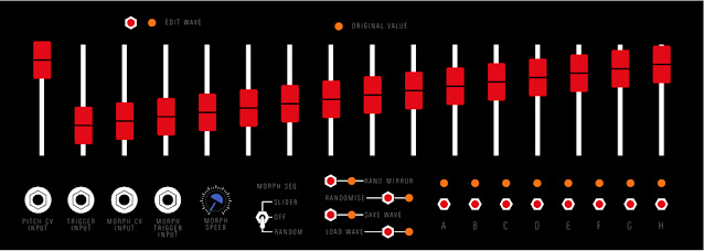
WAVEFORM SEQUENCER
In addition to the main case there is the Waveform Sequencer and Meter box. The waveform sequencer is an idea I've had for a while. It creates a waveform that is split into 16 steps which is controlled by the sliders on the panel. Though that is only a basic function of the unit. It will run in several different modes.
Those modes are:-
- Simple morph - where two separate waveforms are defined and a LFO changes between the two.
- Slider Morph - this is 16 step sequencer which sets the amount of morph between the two waveforms
- Random - the LFO just randomly creates a new waveform on each step - this has two modes on how the waveform is created - total random or random mirror which makes a waveform who's second eight steps is a negative mirror of the first eight which is more like a "normal" waveform.
All these different modes can be control from external source which include control voltages or triggers to control the step sequencer. Waveforms for any of the three Waves (A, B and Percentage) in one of the eight memory locations.
Given that most of my microprocessor skills are limited to Arduino type MCUs, the approach I took for this unit is almost analogue. I have a oscillator module which contains a AD9833 function generator. This gives me an accurate clocking frequency which feeds a 4067, 16 channel analogue multiplexor via a 4510 BCD counter. This multiplexor switches between a bank of MCP42010 dual channel digital potentiometers. The AD9833 frequency is controlled from an Arduino Pro Mini. There's some opamp circuitry which takes the 0 to 5v output of the digital potentiometers and scales this up to 10v and offsets by -5v to give an audio signal. It's as simple as that.
I've used the MCP42010 in the past as it's a good way of making a simple LFO without using a digital to analogue converter.
There's a second Arduino which deals with reading the sliders and buttons along with controlling the all the RGB LEDs on the panel. These talking to each other using serial.
A future enhancement to the unit will be a control voltage output of the slider states along with a trigger to use as a step sequencer within other parts of the Expanse.
One of the funniest mistakes I have ever done was on the Waveform Sequencer. I didn't put an output on the front panel. Most of the work for this unit focused on the front panel which relates to one of the Arduino's and not the waveform making one. This is what I put the omission down to. Well that is my excuse. The output is on the rear panel which is fine in reality as a cable comes from here to the Expanse where the signal is then modified.
METER BOX
The Meter Box combines a basic oscilloscope using a Raspberry Pi Pico with some minimal input electronics to clamp the voltage to the Pi Pico's accepted voltage level of 3.3v. This has two channels coming into it and the results are displayed on the small colour screen. There's three controls for each channel - an attenuator to scale the input signal, offset to move the voltage around the screen and a sample rate control.
The other part of the Meter Box is two analogue meters which have two controls each. One is the voltage range to display which is 10 or 20v and the other control will hold the maximum voltage. Note that 10v means -5v to +5v and 20v means -10v to +10V.
Bother the sections have a loop output from the inputs to avoid not having enough connections.
BANANA SOCKETS
I've chosen to continue the use of banana plugs for the Expanse which I started to use on the SBE2. I think they're ok as a connector though the ones I have purchased are constantly breaking.
The colour code for these comes from the Bucla "standard" which is as follows:-
- Red - control voltage output
- Green - trigger / gate output
- Blue - control voltage input
- Yellow - Trigger / gate input
POWER SUPPLY
The power supply is a linear transformer type in a separate case. I did try some buck converter types for this project in the early stages of testing but found them too noisy. I attempted to fix this noise but I didn't really want to go down this rabbit hole at such a late stage. I will look into solid state power supplies in the future but I do prefer using a transformer to take the main voltage down which also gives isolation as well. Sure they are big, heavy and inefficient but I don't have a shortage of room. What I would look at in the future is combination of transformer to knock down the mains to a smooth dc voltage and then buck converters to achieve the desired voltage rails needed for the project.