 |
| UM27-LCU - Overall View |
 |
| UM27-LCU - close view of controls |
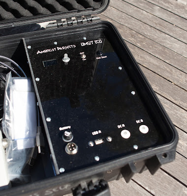
These unit are designed to control two light units. One is a standard 5v USB type light and the other is a specifically modified 60 led unit. The two units are essentially identical thought the self contained unit has it's own 9Ah SLA battery and protection electronics.
These simple unit uses pulse width modulation derived directly from the Arduino Nano processor and controls two current limited led drivers to control the intensity of the connected lights.
The smaller unit has a 4 pin 12v dc input which gets it's power from the Video Monitor unit which has a 9Ah battery or from one of the UM19 battery units when using a small adaptor cable. The unit is capable of running from 10 to 30vdc on it's input thanks to the use of buck converters on the power line.
As part of making this unit I wanted to try using both an organic light emitting diode display and also a rotary encoder for data entry. The rotary encoder has both a switch when pressed and also contains a RGB led in it's shaft. A little over kill but great to try out.
The OLED display is quite simply connected via the I2C connection of the Arduino making a total of 4 connections with 5vdc and ground. Several libraries exist for the Arduino to control these types of 128x64 pixel OLED displays. The rotary encoder was slightly more complicated because I didn't want to use an interrupt based method of reading the clicks. I simply used a polling method as I was not concerned with missing steps. I removed the indent part of the hardware to produce a smooth motion. My concern with using interrupts was that I would upset the display of the OLED which is not a simply process.
The lights are simply controlled using two PWM outputs from the Arduino going to two Led driver boards which have PWM control inputs. The intensity of the lights doesn't work out to be linear but I don't really care about this as I simply wanted a method of controlling the lamp from totally off up to totally on. As long as they were consistent in intensity which they are.
The rotary encoder changes the light intensity when rotated clockwise or counter clockwise. The range is 0 to 100 with 0 being off and 100 being fully on. The value will loop around should you go past the lowest and highest values. This seemed a good method of quickly going from highest and lowest values as the speed of which the values change is not fast mainly due to how slow the OLED display is at being written. The display turns off when no data has been changed for a couple of seconds. You don't want an extra glow caused by the display in your timelapse shot.
Pressing on the push button, which is part of the rotary encoders shaft, will change the current lamp to the other lamp and successive presses will alternate back and forward between the two output options.
One of my challenges for the small unit really came in the form of the case and in particular the mount for the OLED. It was a great challenge for me and the cnc router. As you can see the OLED has a black surround. This is a piece of 4mm acrylic which was machined on the rear to have the correct mount holes and display cutout for the OLED display. This display was then hot glued into place. This assembly was this simply placed into a similar sized hole in the ABS case front plate. I could have gone one step further which was to make a clear lens to sit in front of the display as it currently open to the air.
As you can see here there are two units. The small ABS cased unit is the externally powered unit or UM27vB and the larger black cased unit is the UM27vA. They operate in identically the same way. The self contained unit has an extra DC output and internally has all the necessary hardware and software to manage the sealed lead acid battery. The electronics take up less than half the space in the case as the remaining space was created to store the other light control unit along with all the lamps and cables.
