


 |
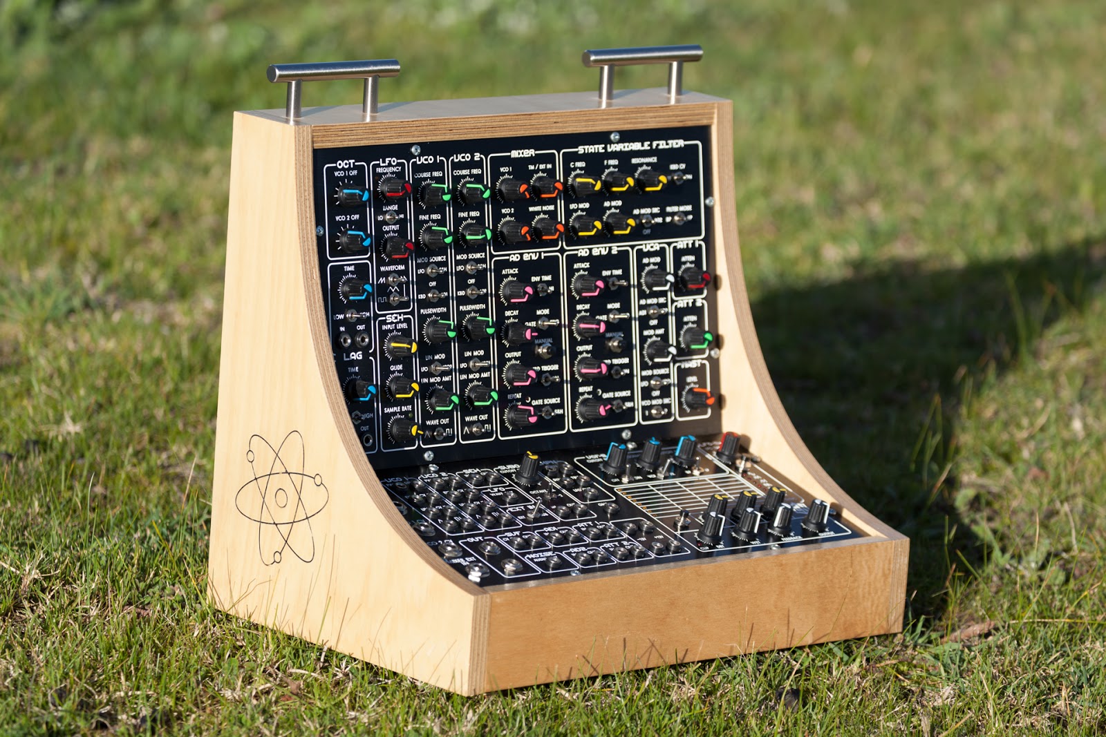
| The Therematron v3 at one with nature |
The upgrade to the Therematron, done a few years back was a great extension to the already wonderful Music From Outer Space's Soundlab Mk2. My execution was hasty and rather messy but the really annoying problem was the bleed which affecteds the pitch of the VCOs that came from the LFO and ADSR.
I'd attempted to fix this pitch issue before by enhancing the power supply to be ultra-smooth but this proved fruitless. The issue was that the voltages coming in via the Coarse and Fine frequency controls on the panel were dirty with the signals of the LFO and ADSRs. I removed this incoming voltage and used my bench power supply to supply the power and the situation improved immensely. I designed up a small power supply which delivered the required voltage. Thankfully I could use the incoming dual rail 12v for the rest of the unit and put in 9v regulators for this VCO power supply. It is very smooth now and makes the Therematron a more usable unit.
In reality this was just one of the issues. As mentioned I threw this upgrade together and used inferior preassembled cabling which was not of good quailty. I use dupont header cables in this unit, so I decided I needed buy some decent wire and make my own up.
Other issues included the layout of the PCBs within the case. The original design had the Soundlab PCB mounted to the base of the unit. This board has almost 100 single wire connections on it and the location is not easy to access. I decided to move this PCB to the rear of the case where it is now fully accessible.
The initial upgrade included a second VCF. My first attempt at a VCF was a very simple design that Ray Wilson (MFOS) had in his Analog Synthesizers book. This didn't work well so I decided on a different type of VCF, a Steiner VCF design from Yves Usson of YuSynth fame. This is nicely unpredictable and most usefully different from the Soundlabs SVF. I want to say here is that the original VCF board was still mounted inside the case as it was difficult to get it out. It's now out !
The second LFO, based around a digital potentiometer driven by an Arduino ProMini, was a little adhoc in its wiring and mounting. This has been greatly improved with the LED display and button now being directly connected to the LFO board as opposed to originally where I had a second ProMini sending data back and forth between the LFO board. This was not a reliable approach. Now the display board is simply a 74HC595 serial to parallel converter with a LED on each output. In addition to this hardware upgrade I also improved the LFO code so that the external Trigger In and Sync In controls work. They're not perfect. The Trigger In will listen for a pulse and restart the waveform with each pulse and the Sync Input will change the speed of the LFO based on the input voltage. The caveat with the Sync In is that I can't read negative voltages on the Arduino so it only reacts to positive voltage changes which is nicely unpredictable.
The original upgrade saw the removal of the Echo Rockit, the PT2399 based effects unit from MFOS. This didn't really do it for me as it was too lofi. No problem. I had good experience with the Experimental Noize FV-1 chips and I designed a unit around their SKRM modules. The signal flow out of the Soundlab module was to have a way of changing the order of what's next. I have the Steiner VCF and effects unit hard wired in but I wanted the ability of swapping their order. So I came up with something using switches which didn't really work in the end due to the complexity. One of the added features was a feedback control which took the effect signal of the effects unit back into the Steiner VCF. This didn't work at all. The upgrade for this section was based around removing the complicated switches and replacing them with a PCB which had four DPDT relays on it. This works really well. This makes the wiring simpler as well as I only have a couple of wires to the front panel to control the relays. Best of all the feedback control now works though you have to be careful.

The Therematron gets its name from the original design which had a Theremin in it. Big Fail. There was too much noise floating around inside the case for that to ever work. So the Theremin board was removed in the first upgrade but the front panel controls still existed. This "final" upgrade sees the Theremin controls removed and replaced with four new modules.
There are two Octave modules. These put out -4 to +4v volts for the VCOs. I often use the Therematron with an Arturia BSP sequence which outputs control voltages. This unit is setup to output 1v per octave control voltages. In use I found that changing octaves on the Therematron was down to retuning which can't really be done in the middle of a performance whereas now I can simply switch up or down. This schematic I took from Elby Designs' Octave Transposer.
The other two identical modules are Lag Processors which allow me to slew any control voltage. This can be anything from smoothing a LFO waveform to creating Portamento on the pitch of a VCO. This design was based on the MFOS RC Lag processor.
I've checked all the functions and found a couple of mistakes but they were easy to fix and so far it works quite well. I also made a small modification to the Soundlab PCB which was a resistor on the VCA's Modulation input from the LFO. The signal level here was quite light on but now it will take the sound to almost nothing when the control is fully clock wise.