

 |
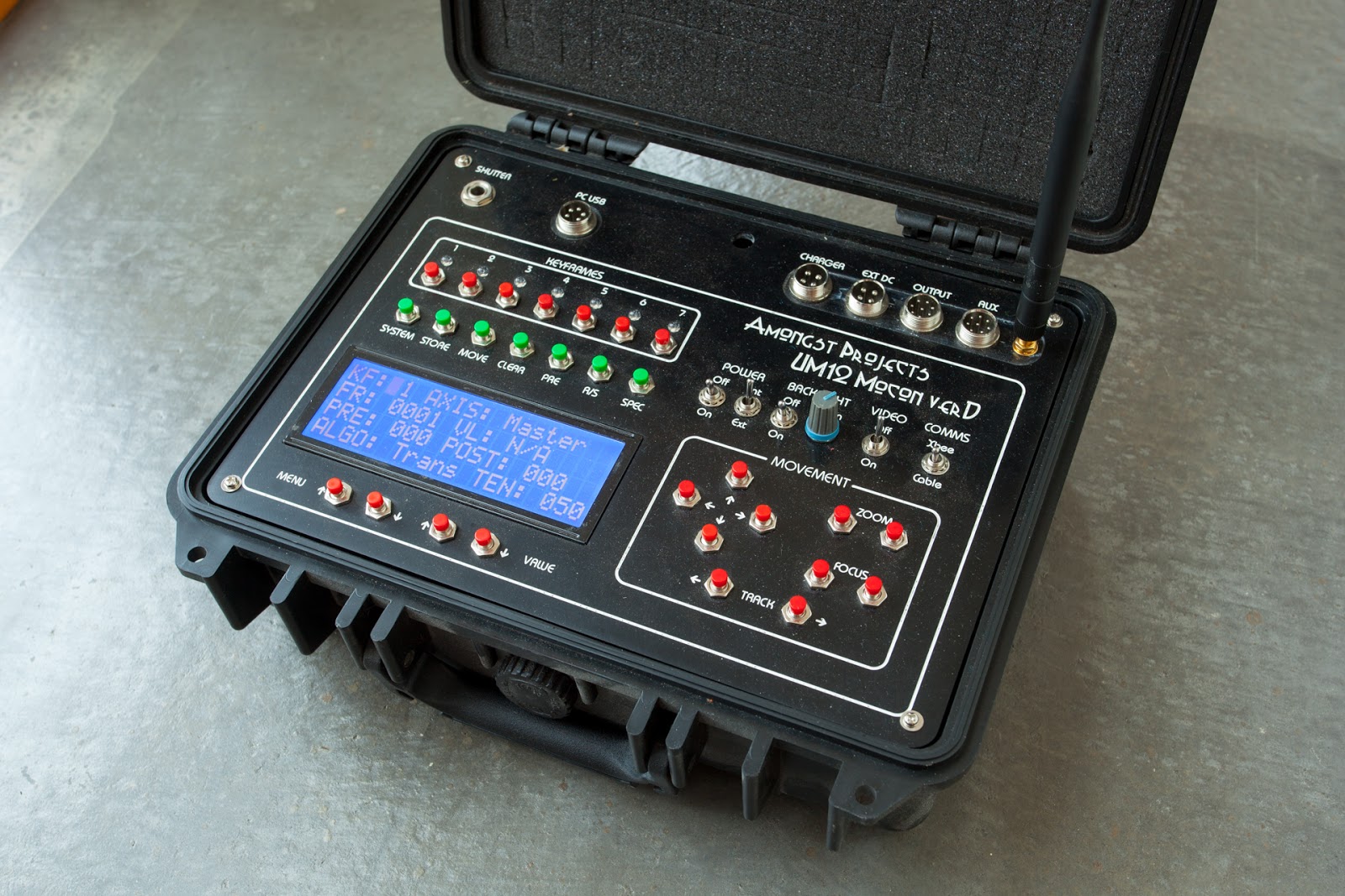
| UM12vD Mocon Hand Controller |
The Hardware
The UM12 hand controller is based around an Arduino Mega2560 processor. The Mega2560 uses the larger Atmega 2560 which has more RAM and digital inputs and outputs to name just a few.
The UM12 hand controller is based around an Arduino Mega2560 processor. The Mega2560 uses the larger Atmega 2560 which has more RAM and digital inputs and outputs to name just a few.
The various pushbuttons are simply read via individual digital inputs with hardware debounce by using a 100nF greencap and 10k resistor on each button.
The display is 20x4 large display which is connected to the Atmega2560 in 4 bit parallel mode.
The leds are RGB leds controlled via two TLC5940 PWM multiplexor chips. This helped reduce the outputs needed to control these lamps plus gave greater control over intensity. The TLC5940 connects to the processor using 4 data pins.
The hardware update from version C of this unit was:-
- Multiple vero boards replaced with two cnc routed printed circuit boards
- Removal of video monitor unit into it's own case
I've used some EEPROM to store shots into a small memory bank. The EEPROM is not affected by power removal. You can store 7 shots simply because there are 7 keyframe buttons for an simple control interface. I have written three PC based transfer programs to allow for uploading and downloading of shots for longer term storage along with a small program which can display the curves of each axis.
The communications between the Hand Controller and Master Controller (dolly) is via a Xbee 1mW transceiver with external aerials. This was the most affordable at the time I started this project. I would now look at Bluetooth.
There is shutter controller hardware on this unit but the software is not implemented to use it.
Hand Controller Software
The purpose of this unit is to control the initial movements of the UM11 dolly and create keyframes for movement points. No movement calculations are done on the Hand Controller but are calculated on the Master Controller. The master controller's processor is a ChipKit Max32. This was chosen because of it's large SRAM memory and also processor speed which is 80Mhz. Again, if I had my time again and started this project now I would simply go for something a Raspberry Pi or Arduino Due.
The unit can have up to 7 positions on each of the 7 axes.
These axes are:
- Track
- Pan
- Tilt
- Focus
- Zoom
- Interval
- Exposure
There is also another control axis called Master which is a easy way of storing data in all the axes at one press of a button.
The start and end keyframes of 1 and 7 are a given value. The shot needs to start somewhere and end somewhere. These keyframes will be set to the minimum frame of 1 and the maximum frame of Total Frame Count. Each keyframe for each axes has several parameters. These parameters are:-
- Frame
- Position
- Pre Hold
- Post Hold
- Transition Type
- Tension
Frame is the frame number at which is axis keyframe information will take place.
Position is a value which is relevant to the axis type. All the motor values are relative to the home position and can range from -65000 to 65000 again depending on the axis. The home position is also a relative value as the dolly has no absolute values of position. The Interval andExposure axes are not motor axes so their Position values are different. The Interval axis ranges in seconds from 3 seconds up to 5 minutes and the Exposureaxis ranges from 1/30 of a second up to 30 seconds in steps the same as 1/3 stop steps within a camera.
The PreHold value is a value in frames for which this keyframe position will be held before the Frame. Likewise, the Post Hold value is the number of frames that this position will be held after the Frame. Keyframe 1 doesn't have a PreHold and Keyframe 7 doesn't have a Post Hold.
Transition type if what type of move will be performed from this keyframe to the next active keyframe.
The options are:-
- Transition
- Smooth
- SmoothB
Transition is a default and useful curve. By default without any post hold frames it will be linear. Whereas if you place a post hold then the following curve will have an ease out applied to it. Should you want to create a keyframe where the camera must pass through on it's way between two other keyframes then you choose the Transition type for a smooth transition.
Smooth and SmoothBare quite similar to the Transition type and provide a nice smooth start and end to a move. The difference between the two is in the Tension value and how this is applied. With Smooth the tension value represents a point placed at a percentage between the two points whereas SmoothB is simply a number of frames from the current keyframe for this imaginary transition point.
The curve calculations are Catmull Rom and the three options above all use the same calculations for their curves. For intensive purposes you could happily use the Transition type for all moves but the SmoothB in particular lets you do some more technical moves that may help with getting around issues of an natural move. To some degree this is an experimental option.
Finally the Tensionvalue, which has really been explained above, essentially sets the position in frames from the current frame for where this imaginary transition point exists. So unlike using Bezier curves which have 2 dimensional handles for each point, the Catmull Rom is simply a curve system whereby a line moves smoothly through a point. From my perspective the Catmull Rom system is easier for the more simple shots that a timelapse photography rig would use. The other issue with using Bezier curves is the limited text display wouldn't give any useful feedback. I believe Bezier Curves really need a display which can show the line being produced.
The System Control pushbuttons
There are seven function buttons underneath keyframe buttons. Working from the left to the right.
These are:-
- System
- Store
- Move
- Clear
- Pre
- R/S
- Spec
The System button changes the mode of the unit between the Keyframe Menu and the System Menu. The System Menu is where system and shot based parameters are set.
Following are the current System Menu items:-
- Shot Store
- Total Frames
- Frame Split
- Shot Direction
- Shot Pre Delay
- Sub Frame Start
- Sub Frame End
- Screen Saver
- Frame Rate
- Shot Type
- Park rig at end
- Axis Limits
- Preview Video
- LED intensity
- Frame Increment
- Hold Increment
- Slice Count
- Motor Delay
- Track Engage
- Pan Engage
- Tilt Engage
- Focus Engage
- Zoom Engage
- Buzzer Enable
- Track Simu
- Safe Move
- Axis Key Jump
- Move To Home
- Set Home Pos
Shot Store - This has it's own sub menu. This is where the user can Store, Load, Clear, Send To PC and Receive From PC any shots stored in the 7 memory locations. Using the Value keys to scroll through these options and then select one of the 7 Keyframe buttons to complete the operation. The exception here is the PC transfer options which just rely on any of the keyframes buttons to be pressed because these PC transfer functions will send or receive all 7 locations. The keyframe leds will display as Red to show an empty memory location and Green for a stored shot.
Total Frames - This is the total number of frame for the current shot. This is limited to 4000 frames which is due to the size of the SRAM on the ChipKit Max32 processor within the Master Controller.
Frame Split - This is a useful function which will automatically assign a Frame number to a Keyframe when you Store the values of the Keyframe. If this is turned on then the Frame number assigned to a keyframe will be in the middle of the previous and next keyframe. For example if you have 1500 frames in the shot. KF1 will be at 1 and KF7 will be at 1500. If you store any keyframe at this stage it will be assigned 750. And if you keep going and store a keyframe between that previous keyframe and kf7 then it will be stored for frame 1125. If this function is OFF then you will need to enter a Frame number manually. You have to pay close attention to this because by default it will store it at Frame 1 and I cannot predict what the system will do if you have two keyframes on the same Frame ???
Shot Direction - Simply has two options of Forward and Reverse. If Forward then the shot will run from frame 1 to 1500 using the example above and if set the Reverse then it will run from Frame 1500 to 1. Note that in reality it will run from the values set in Sub Frame Start and Sub Frame End.
Shot Pre Delay - This is a delay seconds before the timelapse shot starts running.
Sub Frame Start - This is the actually frame from which a timelapse will start from. This is useful if you are shooting a long shot in multiple sections where each section is at a different time of day.
Sub Frame End - As above but for the end frame number.
Screensaver - This switch will turn the screensaver off and on. It turns off the backlight on the LCD display after 5 seconds. This function is a legacy from when the unit also powered the video monitor and I tried everything to lower the drain on the inadequate battery. I leave this off mostly.
FrameRate - This is the framerate at which the realtime preview will run. It has a valid range from 1 to 60 frames per second.
Shot Type - The value has three options - SMS meaning Stop Move Stop which is the default timelapse mode, Stop Frame which is linked to the use of a push button on the Aux input on the Hand Controller and will move one frame and wait until the button is pressed before doing the next frame and Continuous which is a experimental mode utilising the real time preview where the frame is exposed moving at speed it would during a video type move. The amount of wobbly in the system really does make this unusable but could be tried on a fast shot to add blur.
Park Rig At End - Simply a function to return the dolly to the home position and point the lens down.
Axis Limits - This will limit the movement of all motor axes to those set within the software.
Preview Video - This enables the use of the Magic Lantern firmware within the Canon 5D Mk2 camera to turn the recording of video off and on during a shot preview. The function controls the half shutter connection which the Magic Lantern firmware interprets as a control for video recording.
LED Intensity - This sets the backlight of the LCD and the RGB Leds. There are 4 options - Bright, Normal, Dim, Dark - which range from full intensity down to dark night intensity.
Frame Increment - This is a value which sets the increment value of user input values with the keyframe displays and it ranges from 1 to 100
Hold Increment - This is similar to Frame Increment but is specific to the values of Pre and Post Hold
Slice Count and Motor Delay - are system level values which adjust the speed at which the Realtime Preview runs at. The Slice Count is the number of slices per second the motor moves and the Motor Delay is a very small delay in milliseconds between motor steps. These could be used to great use for doing realtime moves for video to slow and smooth shots. The realtime preview is not perfect but works quite well to give an idea of what your shot will look like when finally composited into a video.
Track etc Engage - This turns the axis off or on. The motor will be engaged but will not move.
Track Simul - This is Track Simultaneously. I've found that moving all axes at once does introduce stutter in the track so I've added this option to move the track separately to the other axes when the rig moves. Turn this on and the Track will move with the other axes. Turn it Off and all moves will start with the Track and once the Track is at it's destination, the other axes will move.
Safe Move - When Safe Move is turn ON the Pan axis will move to it's home position first and then once the other axes has arrived at their destination the Pan will move to it's destination. I found this to be a useful function when filming close up objects and avoids the edges of the Pan assembly hitting objects.
Axis Key Jump - This OFF and ON function related to user inputting of information within the Keyframe Menu. With this function turned ON, the keyframe display will change to the Axis that you move with the arrow keys. With this Function OFF the keyframe display will not change.
Move To Home - By selecting this value to ON the rig will move to it's programmed Home Position
Set Home Pos - By selecting this value to ON the current location of all the Axes will be set as the value 0 or Home Position.
So that is all the current System Menu items within the Menu items but there are a couple of other features which will be run if you select Function buttons while in the System Menu.
To move around the Keyframe screen you use the Menu Up and Menu Down buttons and to change the select value you use the Value Up and Value Down buttons.
If you press the SPEC button the Hand controller will request the current shot data from the Master Controller. This function is mostly used when you have turned off the Hand Controller or a bug has caused a freeze within the Hand Controller. If you press the STOREbutton while in the System Menu you will display the Real Time Clocks Time and Date as well as the current voltage of the interval battery.
Back to the other Function buttons. The Store button is used to Store current axis positions into the selected Keyframe number. The only value that actually gets stored is the Axis position and Frame number. The Frame number will be 1 if the Frame Splitis OFF and it will be the middle Frame value if Frame Split is ON.
The next button to the right is the MOVE button. The button has two functions. The first press will give you the option to Move the rig to any active Keyframe of any Axis. You need to have selected the Axis you want first by using the Menu and Value buttons before pressing the Move button. Once this is pressed the rig will do a calculation and then move all axes to that position. The Track Simul and Safe Move system values will affect how this move is performed.
The second function of the MOVE button is to move the whole rig to a specific Frame number. This is a useful function to find where the rig will be at any time during the shot. The Value Up and Value Down buttons will change the Move To Frame and once you have chosen the Frame you wish to move to you hit the MOVE Function key again. If you wish to cancel out of this function then you hit theSPEC button.
Moving along, the CLEAR function key simply will clear the contents of any Keyframe. There is a small bug within the system whereby if you have created a keyframe using the MASTERaxis then you cannot delete a keyframe. Yes it is a problem but personally I've just worked my way around the issue. I find that the best way of using the MASTER axis is mostly for KF1 and KF7 and from there on I will only use the individual Keyframes within an Axis. Often this is the case where you want the TRACK to move at a constant pace and the PAN and TILT to do their thing. A common basic move for timelapse.
The PRE key is Preview. The is the function to do a realtime preview of the timelapse shot. Simply pressing the PRE key will initiate the preview. The first step is to see if the rig can move at the speed requested. There is a maximum speed limit on the rig. The rig can go faster but will have less fine movement. This is something that has to be set within the dolly case and has been set at an optimum already for timelapse. But the controller will either start moving to the beginning of the preview if all is OK or return with an error if it is too fast. I find that if it can't do the preview move then the rig is probably moving too fast anyway. The Hand Controller will then ask you to press the PRE button again to start the actual preview movement. You can cancel a Preview during it's run by pressing the Preview key again.
R/S is Run and Stop. This is where you will start the timelapse shot running. Pressing the key the first time will move the rig to the start of the shot. Remembering the actual start of the shot is what is defined in the Sub Start Frame or the Sub End Frame depending on what direction the shot is running is based on the Shot Direction value set in the System Menu. Once a shot has started it can be stopped by hitting this button again. It may take a couple of hits but be patient as it will not register the Stop until it has completed the current frame exposure and movement. But hitting the key several times isn't a real issue.
By pressing the SPEC key while in the Keyframe Menu will put you into a special time calculation function screen. The idea behind this function is to allow you to calculate when to start the shot running if you want the rig to be in a certain position at a certain Frame number. Use the Value Up and Value Down buttons to change the Frame number. The Frame Number will start from the where the rig is currently located. The Time Start value will be the current time that you entered this screen. You can change the Hours value by pressing KF1 to increase and KF2 to decrease, change the Minutes value by pressing KF3 to increase and KF4 to decrease the value and finally using KF5 to increase the Seconds and KF6 to decrease the Seconds. The calculation should be immediate but are done on the Master controller so you can't do it without the Master controller being active.
Just a note on the RGB leds above the Keyframe Buttons. During the Keyframe Menu mode these reflect whether the associated Keyframe has a store value. If the Keyframe Display is showing Master then the keyframe leds will be Green whereas if the keyframe display is showing a specific axis it will display active keyframes as Blue.
The other front panel controls include the Axis movement controls at the bottom right of the front panel. This is where you move the various axes in the chosen direction. Simple !.
Above the axis movement keys we have power switching mostly. Starting on the left is the Main Power button followed by the Internal and External power input. When set to Internal the internal battery will power the unit and when set to External the power will be taken from the Ext DC socket at the top of the panel. This socket is wired in my standard 12v 4 pin plug configuration which is positive on the bottom and negative at the top. Next is the LCD backlight controls. The Off and On switch controls the power to the backlight and the Intensity controls the Contrast which is adjusted depending on the angle or viewing. The Video Off and On switch is no longer used as this unit was constructed before I moved the video monitor to it's own case. The Comms switch changes how the Hand controller talks to the Master controller. Should the wireless communications fail for whatever reason, a cable can be connected from 8 pin socket at the top of the panel named Output to the similar connector on the Dolly named Comms.
Running along the top are various sockets. Starting from the left is the Shutter connector. This is a 6.5mm or 1/4" stereo socket. This is wired for half and full shutter connection. This is not current used by the software. It was installed just in case I wanted it for the future. PC USB is the connection from the Arduino Mega2560 for programming purposes and has no use during operations. Charger is for connecting the UM16 SLA Battery Charger to charge to internal sealed lead acid battery. Ext DC is for connecting an external 12v dc power supply should the internal battery become flat. Note that current software will complain the battery is flat but will not turn of the machine off. Output is a for connecting the Hand Controller to the Master Controller via a cable should the wireless connection not work. Aux is currently only used with the Push Button controller for stop motion timelapse but also contains other inputs and outputs connected directly to the processor for possible other future enhancements. And finally the Xbeeconnector is for the aerial to increase the radio transceivers signal for the two way communications between the Master Controller.