 | |
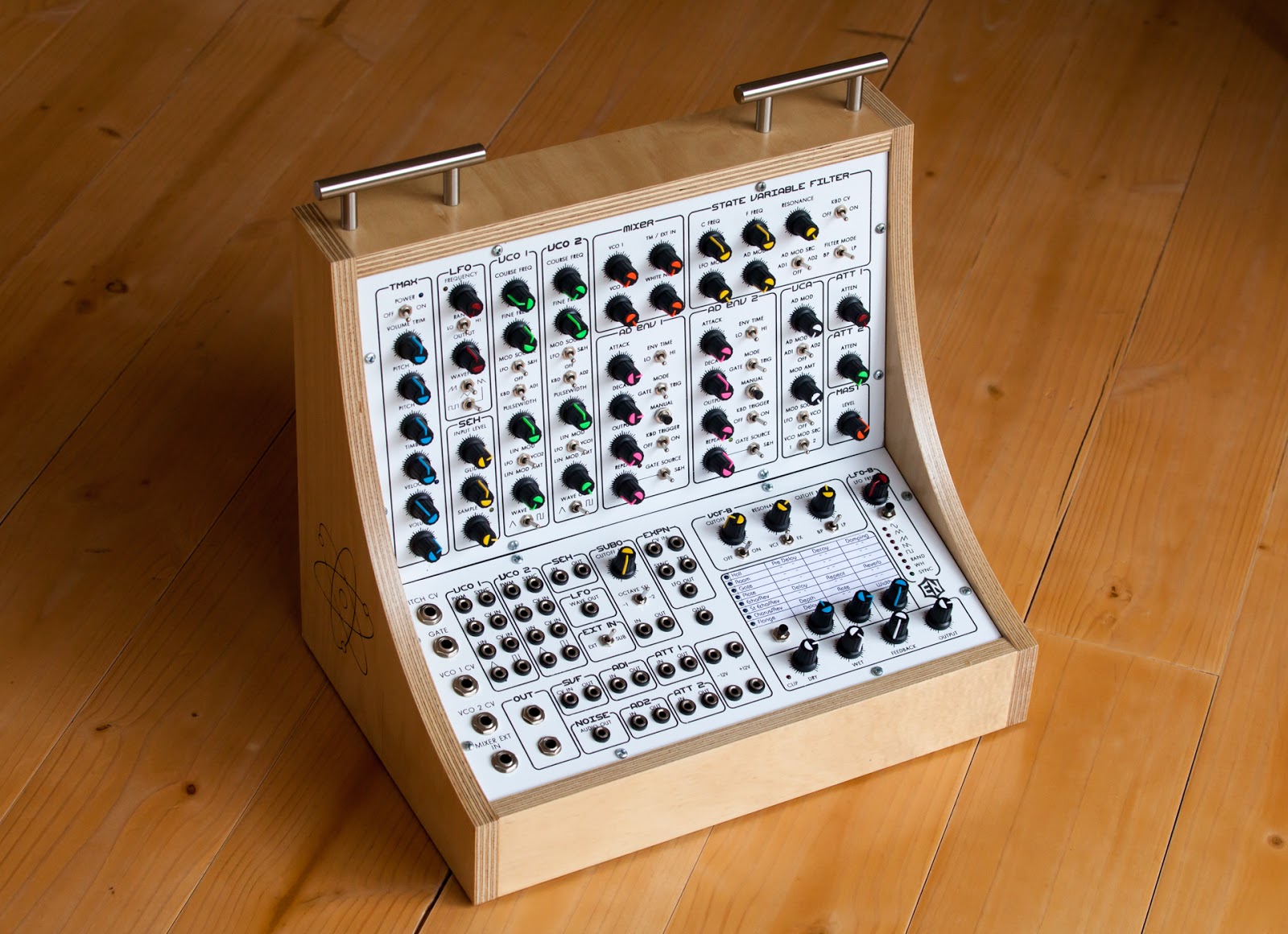
| The Therematron NOT - current model |
So the original Therematron design was based around MFOS Soundlab Mk2 designed by the late and great Ray Wilson. Along with this wonderful 2 oscillator synth I was to use Ray's Echo Rockit digital delay unit and the icing on the cake would be the PAIA Theremax theremin. What a wonderful machine it was. In theory anyway.
It was quite a while ago that I started the original Therematron. I started this back in August 2014 or possibly earlier. Looking back at my daily log I read that it wasn't until February 2016 that I finally got back to trying to make the Therematron work. I had got the Theremax working inside the case but there was something wrong with the Soundlab. The wiring of Ray's boards isn't easy. I fully comprehend that he designs his boards to be as small as possible but in the process most potentiometers and switches don't have their terminals next to each other and can often be part of a chain of wires to get them all connected hence the wiring of a single board synthesizer is quite messy. Add to this the limited space inside the case and problems become quite difficult to solve. Hence I appear to have put off getting this unit running considering it was in late 2014 that I had made the case up.
Moving along to March 2016 and several other distraction projects later, I was battling with getting the VCOs to be stable. The issue was and still is to a degree, an amount of the envelope generators LFOs coming through. It must be something to do with the earth line as far as I can tell. I'm not working on solving this issue as I'm happy with where it is. Someday I may come back to this.
I made this funky light display on the rear of the Therematron as just something to do and it also affects the power supply but to a greater degree that I can't use it. I could possibly try putting in a power regulator on the light display to help alleviate any affect it has on the other parts of the power circuit. Since this is only seen from there rear I think I will just put a 9v battery inside to run it when I use it live. Seems the simplest solution to me.
 |
| Rear panel atom animation |
It was during this period of finalising the Therematron that I could not get the Pitch on the Theremax working when installed in the case along with all the other electrical noise. I could get a reduced output from the Volume antenna. Quite disappointing. I was also disappointed by the quality of the Echo Rockit. I knew that it was "lo-fi" but it was lower fi that I was happy with. So there Therematron went back on ice and then we moved to the country. It was February 2017 before I started what would become the Therematron NOT !
Having moved into the new house and setup a new studio I returned to where I left off back at the Blackwood Studio and started work on the Therematron NOT! in the new Wahroonga Studio. I decided that I would remove the Theremax and replace the Echo Rockit with an Experimental Noize module. Quite a bit of work but I wanted to get this machine working. The Theremax may still appear in a new case later down the track.
This upgrade couldn't be simple could it ? Oh No. I designed an effects chain which not only had the EN SKRM module but in addition the module contained an analogue feedback path which, for extra variation in sound, includes a VCF and a LFO for VCF modulation. The idea being to emulate to some degree what the Echo Rockit could do and more.
The EN-SKRM module was mostly straight forward as I had already made the UM-XN1 guitar effects unit. Where the Therematron version differed was the addition of a feedback path which routes the output of the unit back to the input but via a VCF. This VCF can also be moved within the signal path. It can be changed from being in the Feedback path to being at the start of the effects unit. Reasonably straight forward in theory.
So a LFO. I wanted to make a LFO based around an Arduino controller and a MCP41100 digital potentiometer. These potentiometers have a 256 level 100k pot which are controlled simply using SPI from a microcontroller. So the idea came to me to use the Arduino to create several different waveforms as a CV to output as a modulator. A fellow electronics nut and musician, Abram Morphew, had done all the work already. Abram had created what I was after as far as the waveform creation using interrupt timers on the Arduino. Some small modifications to his code made the digital pot do all the work.
The LFO has another Arduino which controls the selection and display of waveforms on the front panel. The EN-SKRM module also has a similar Arduino panel controller. I decided to use a simple serial protocol to have the panel Arduino talk to the LFO Arduino which appears to work well after some initial problems. I originally had the serial communications working over the Software Serial library, which is a software method of creating a serial line on any Arduino digital connection but the downside of this is there is no UART with a data buffer. Hence, if you do not monitor the software serial connection you may miss something. The hardware serial ports on the Arduino have a buffer where data is stored until read or until it's full. This way you don't have to be as concerned about servicing the serial port.
The VCF I wanted to be cheap and dirty. I chose a design Ray Wilson had in his book, "Make: Analogue Synthesizers". It was based around a single LM13700 chip. The only problem was it was too dirty. Aghhh ! Now I need to find space and another design. I was getting bored by this stage. I trawled through links to find the YuSynth site. Here I found a Steiner VCF that was not only a good sounding VCF but there was also a single sided PCB design. So I set out and cut myself a slightly modified version of this VCF. I moved the power connectors around and change the ins and outs to suit my connectors.
 |
| The new VCF, LFO and Effects section |
So now I had a good sounding setup. I needed to create a new bottom panel for the Therematron. Like usual I spent a good day in Freehand moving things around on the screen and realised that I had some spare real estate now that the Echo Rockit has been replaced. "Let's put in another module !" - I heard my evil twin shout. But what ?
I had been playing around with some simple circuits from my copy of Nicolas Collins, Handmade Electronic Music, is recent months and I remembered where he describes using a 4017 at audio speed. A 4017 can be used as a divider. It's in reality a decade counter. So it gets me thinking about using a 4017 to make a sub-oscillator. Why stop there. A 4017 puts out a nasty square wave so I put a variable filter after the 4017 and now I have switchable 1 or 2 octave sub-oscillator with a low pass filter on it. That fits quite nicely into the front panel.
 |
| My rather messy schematic for the Sub Oscillator (note power input is +/- 5v) |
It all fits quite neatly. Don't lie ! It's a mess inside there. Do not enter without a guide. It's not perfect as the whole VCF switch around on the effects doesn't quite work but for now I am happy. I've programmed the SKRM module with a basic set of reverbs, echos and modulation effects for now and I can always come back and change these later. The top front panel still has the Theremax controls but the Theremax is no longer contained and the aerials for the Theremax are still there and act as nice handles. Now I just need to use it to make noises !
But the main question is whether this is the end for the modifications after all there's the front space where the Theremax controls were ?
 | ||
| The full rear panel |