| The Flatman and Ribbon - Dual Ribbon CV controller |
|
Talking to artist friend Bernard, who recently decided that spending lots of money on modular synth modules was his new pass time, wanted some other kind of alternative controller. I suggested a ribbon controller mainly because my new Solaris has one and it's a great way to control anything on the synth. As always I head for Google to find if someone else has already done one of these projects. I found a project by Chip at Synth Hacker - http://synthhacker.blogspot.com.au/2016/04/diy-ribbon-controller-cv.html. This was the basis of the unit I was to build.The main focus is making a controller for modular synth units hence it needed to put out a control voltage relative to the position on the ribbon. Going to my trusty supply of Arduino Pro Mini processors you may know there is a lack of voltage output control. There is a method of creating a voltage output using a resistor ladder and several digital outputs but we wanted something a little more accurate and less output hungry. So I chose the MCP4922 dual 12 bit digital to analogue converter (DAC) primarily because Chip used this one in his ribbon controller project. This digital to analogue converter was cheap and has two converters on it. So it was the dual converters on the DAC that allowed this project to easily have two ribbons.
 |
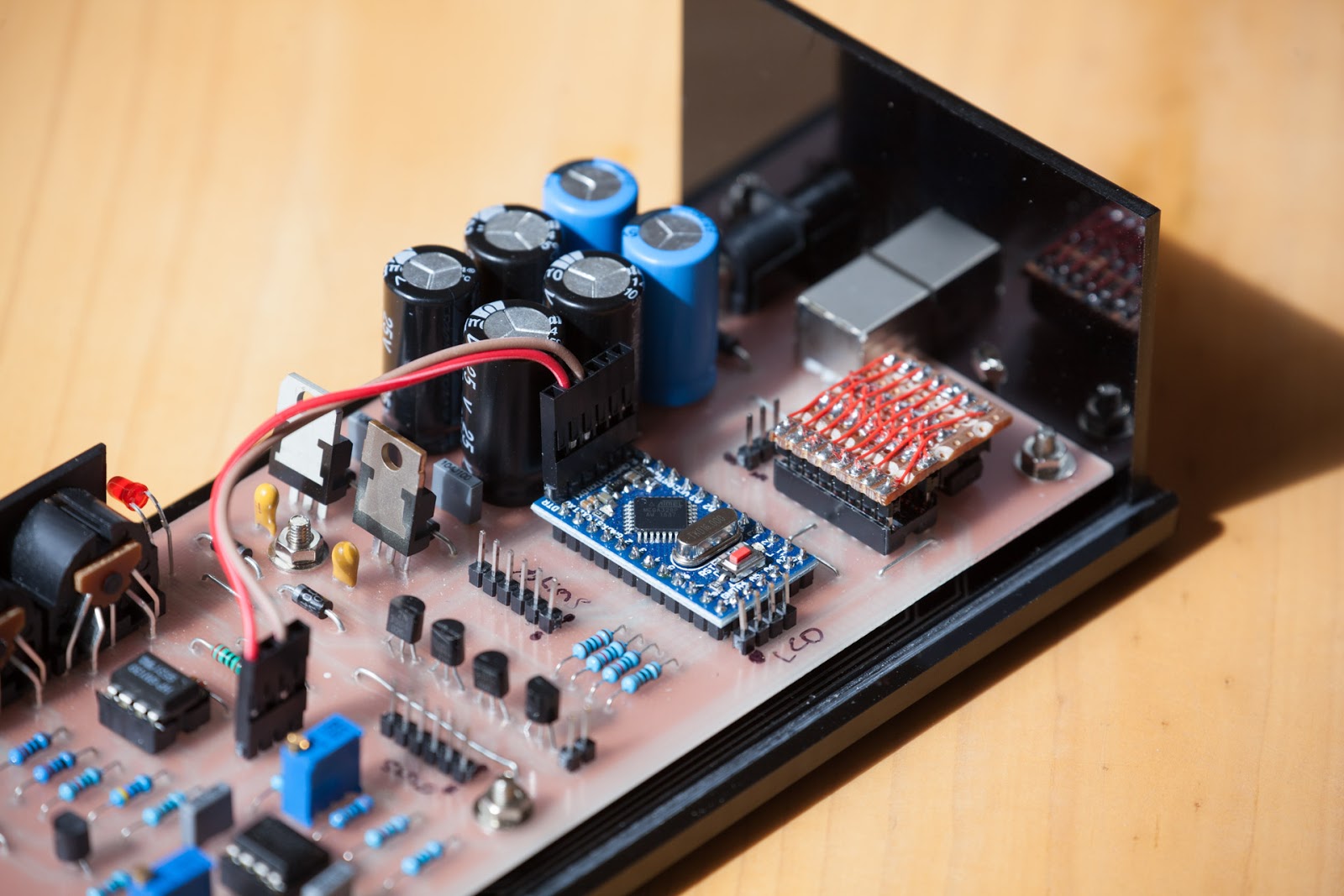
| The botched job of the MCP4922 Digital to Analogue converter can been seen at the bottom left of the printed circuit board. |
The DAC is easy to connect, and thanks to Chip's notes, easy to program. It uses the SPI protocol to communicate between itself and the processor. As mentioned, analogue synthesizers use a control voltage to control pitch and modulators on synthesizers use control voltages as well. These modulators usually range from a negative value to a positive value and use 0v as the mid-point where no modulation happens. To achieve this on the Flatman and Ribbon I used an inverting amp with adjustable bias. Once again Ray Wilson has a useful calculator on his web site which allowed me to calculate the values I needed for this part of the schematic.http://musicfromouterspace.com/index.php?MAINTAB=SYNTHDIY&PROJARG=ELECTRONICS/TECHBENCH/TECHBENCH.php&VPW=1910&VPH=825. Chip wrote a version simple routine which I have used to set the output voltage on the MCP4922 converters. The only issue I had here is probably not obvious in the above photo as you can't see the converter but during the design of the board I needed to create the component for the DAC and for some reason I made the package a DIP-14 whereas it's a 16 pin package. What you see here is the fixup to avoid redoing the printed circuit board.
 |
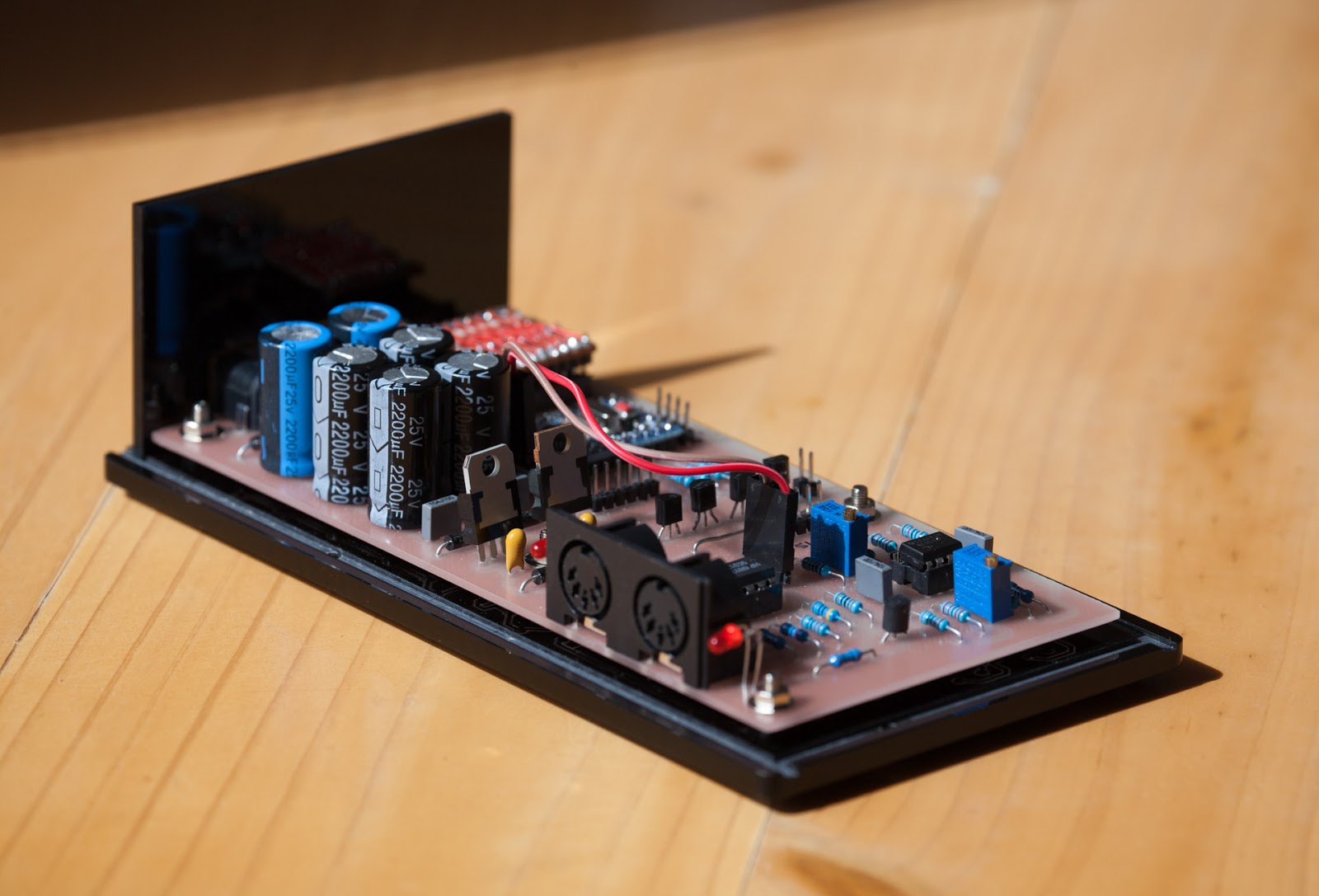
| Showing the back side of the controller unit. The overkill power supply with it's 6 x 1000uF electrolytic capacitors |
The other complex part of the hardware construction was creating a dual power supply to allow for a maximum of -5 to +5v outputs on the control voltages. These power rails needed to be stable as they are source of the outputted voltage to the synthesizer. For 1V per octave synthesizers a simple calculation of 1 volt divided by 12 semitones per octave gives us 0.083 volts per semitone. So this suggests that any slight interference within the power supply would vary the control voltage. Using the 12 bit digital to analogue converter over an 8 bit converter gives us a smoother transition between frequencies especially when using the full -5 to +5 range on the ribbon.I went a little overboard with the power supply. It's based on Ray Wilson's (MFOS) design which I have used before. The Wall Wart Bipolar Supply is a simpler way of getting a dual rail power supply as it avoids dealing with mains wiring. This is because it uses an external 12v AC plugpack or wallwart. I don't think anyone really likes plug packs but working with mains wiring is less appealing plus there is the added cost of the associated hardware. Using Ray's schematic, I replaced the 7812 and 7912 in the design with 7809 and 7909 regulators to give me 9v which is more than adequate for the output voltages needed. If I used 12volts I would be pushing the Arduino's own power regulator to its limit which I didn't want to chance.
 |
| Showing the front panel with the outputs down the left side and the lcd with menu buttons on the right |
The unit has an LCD display with menu buttons. I used a 16x2 backlit lcd display which comes with an I2C interface board attached. The I2C buss uses less wires to communicate between the Arduino and the LCD display. The I2C buss is on A4 and A5 on the Pro Mini. The four buttons are for changing menu items. There's a Menu Up, Menu Down, Value Up and Value Down. It's a design I have used before and works well. Though it wasn't until I'd finished making this project that I realised I had put in extra components that are not needed. For each button I would put a debouncing capacitor and a pulldown resistor. It didn't occur to me that I could use the Arduino's internal pullup resistor's which each digital i/o has. Next time !Next to the output sockets I've put a rgb led associated with each output. These rgb leds are my favorite led at the moment - the WS2812. What makes this leds nice is you can simply string several together and the library courtesy of
Adafruit makes them easy to control. I highly recommend you support Adafruit. I would more if the freight costs to Australia were more affordable. These leds reflect the state of the outputs. The control voltage leds do a colour wheel effect based on the ribbon position. There was a small issue when it came to the software. I use have used one of the processors interrupt timers when running the sample/hold mode but alas the Adafruit library gets upset with me doing this thus during this mode the leds do not function correctly.
The unit includes a MIDI In and Out. Since the Pro Mini has a standard serial interface it makes sense to include a MIDI interface. The unit will act as a MIDI merger allowing all MIDI information coming on the In connector to be thru putted on the Out socket. With the addition of the information from the ribbons. In addition there is a MIDI function which monitors the MIDI in for a MIDI clock and converts this into a pulse on the Aux Output.The outputs on the controller box are Control Voltage A, Trigger A which are associated with the top ribbon. Control Voltage B, Trigger B which not surprisingly are associated with the lower ribbon and Aux Output. Depending on what mode you are running the unit in depends on what the different outputs do.
 |
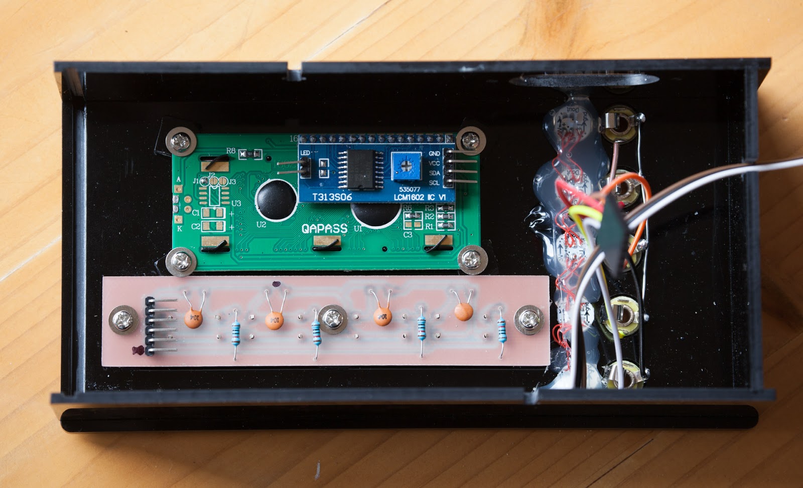
| The underside of the controller panel lid. Shows the LCD at top with it's I2C daughter board, button board at the bottom, the rgb leds and output sockets to the right. |
There are currently 3 modes - Default, Tempo and Sample/Hold. Default mode is simply where the top and bottom ribbons output a control voltage. Their associated Trigger Outputs will either put out a Trigger when a finger is applied or hold the Trigger Output high until the finger is removed. This is the Gate mode and each ribbon can be set independently to either Trigger or Gate. In Tempo mode the top ribbon acts the same as the Default mode but the bottom ribbon will output a pulse on the Trigger Output. The speed of the pulse is affect by the position along the ribbon. Finally in Sample/Hold mode we see the Control Voltage from the top ribbon output a random voltage. The range of the voltage is defined by the fingers position on the top ribbon and the speed at which the random changes is defined by the finger position on the bottom ribbon. By default the Aux Output will always output a pulse based on MIDI Clock and the Clk Divisor value set in the menu.There are various parameters within the menu system. For both ribbons we have:-
- U Lo Volt - sets the lowest voltage value
- U Hi Volt - sets the upper voltage value - note this can be made a low value and the U Lo Volt can be a high value thus creating a reserve direction ribbon
- U Trigger - whether the trigger output is Trigger or Gate - trigger will simply pulse when the ribbon is first pressed whereas Gate will hold the trigger pulse high until released
- U Hold - set this On and the control voltage output will be held at the last value otherwise it will revert to the U Lo Volt value
- U MIDI Ch - this is the MIDI section and this value sets the output midi channel
- U MIDI CC - this is the controller value that this ribbon will output on
- U MIDI low - the minimum value to output
- U MIDI high - the maximum value to output
A set of these menu items exist also for the Lower Ribbon. The only other current parameter is Clk Divisor which is the divisor of the MIDI Clock. The MIDI Clock outputs at 24 pulses per quarter note. The Clk Divisor value will simply divide this number and then output a pulse. https://en.wikipedia.org/wiki/MIDI_beat_clock
 |
| The USB end of the ribbon platform which I am very proud to have made work and look good |
The platform on which the ribbons are mounted was quite a challenge for me. It's made from 19mm plywood just because I had some and it's a nice solid thickness. I wanted to make the final result as clean as possible. I had to mount a USB A socket in the end of the unit along with a printed circuit boards which has a few components and the ribbon connections. So I managed to route a chamber into the end of the platform to contain the pcb. One of the biggest challenges of this section was I had no way of screwing down the small pcb into the 3mm remaining plywood. The only part that I could screw down was the top acrylic piece. So I came up with the idea of making the pcb a tight fit inside the cavity. Then I soldered some small pieces of coiled wired to the bottom of the pcb so that it was levelled out given the usb socket was raising one end. Then I mounted some standoffs on the acrylic lid so that when the lid is screwed down these standoffs hold the pcb in place. The next tricky part was how to glue the two pieces of acrylic which make the side and lid as I didn't want to also have screws in the end panel. So I had to chance screwing down the lid with pcb in and adhering the usb piece of acrylic in place hoping not to adhere something else, notably the wood, in the process. It worked out fine and a very neat finish.
 |
| This the Cut2d shaded preview of the USB end of the platform. The pcb was made to the same shape as the large internal cutout but less 0.5mm in size so that it was a tight fit. |
 |
| These two pieces were routed from 3mm black acrylic and adhered on their joining edge. |