What is the FloriVoxTron ?
 |
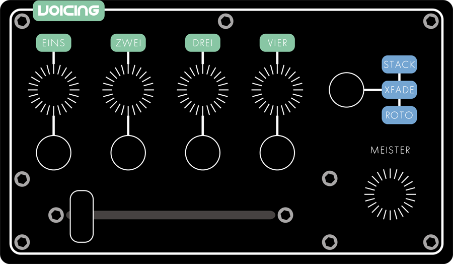
| The FloriVoxTron running wild in the paddock |
Basically, the FloriVoxTron is a sample playback keyboard. It has 16 note polyphony. At its heart is the Robertsonics Tsunami sample player module. This is followed by a familiar format of a subtractive synthesiser, VCFs, VCAs with lots of LFOs, Valve Overdrive and effects units.
If you'd prefer to see a video instead of reading - https://www.youtube.com/watch?v=PYeXDhLF1S8
What's with that name ?
The name FloriVoxTron is derived from another Amongst Projects project. The Florian Vox was a project that was to be a MIDI controlled speech synthesizer with a nod to Florian Schneider of Kraftwerk. The hardware was pretty straight forward as was the programming of the speech patterns but the one major floor was that it was not very fast in responding to commands. This is how the speech chip was made. The intended use of the Florian Vox was for my Kraftwerk cover band at the time and was to be controlled live. Alas the Florian Vox was shelved along with the band. The FloriVoxTron has several sample sets derived from the speech synth and one of the early intentions of the FloriVoxTron was to be a vocal sample player.
Some more in-depth information please !
Working from the source. We have four voice layers. These are named in German (of course), voice 1 being Eins followed by Drei, Zwei and Vier. Being a sample player based sound source, each of the these voices can access any of the 120 sample sets. Each sample set is a set of samples which covers the 36 note keyboard. These voices each contain a VCA to control their own level. The first three voices are mixed together where they pass through a VCF and onto a Valve Overdrive. The signal then goes to a master VCA and an effects module before joining the signal path of voice four and out of the unit. Voice four has a similar path to voices one to three with its own VCF and VCA but no valve overdrive unit.
What makes this unit so different is that the unit is stereo from the start to the end. The samples are stereo, the VCAs are stereo, the VCFs are stereo, the valve overdrive is stereo and the effects are stereo. To top it off the Modulators are stereo as well.
The Modulators
 |
| Graphic of the Modulator Section |
What I think makes the FloriVoxTron a rather unique instrument is its stereo signal path from the start. Though what makes this work to great effect are the Modulators. The FloriVoxTron contains many LFOs. Each Voice VCA has one, each VCF has two, one for the Cut-off Frequency and one for the Resonance, Pitch Control and the effects also have one each. These LFOs are all independent from each other. These are not your standard LFOs, I have called them Modulators because each LFO is in fact two LFOs.
The Controls of the LFO:-
-
Speed - most LFOs need a speed control. The FVT has the addition of a Speed Multiplier control which allows the Speed control to cover a greater speed range.
-
Waveforms - there are ten waveforms at the moment. They are pretty standard - Sine, Triangle, Square, Sawtooth, Ramp, Random and some not so basic ones - Rectified Sine, Chirp4, Quad Square and Quad Triangle.
-
Pulse Width - controls the width of the Square wave pulse
-
Delay - is a one control envelope generator which can be used to delay the start of the LFOs output.
-
Rez - is a backwards Sample and Hold in that as the value is increased the less samples are taken of the LFO's waveform
-
Wave Delay - this is another way of doing a stereo LFO without the Pan LFO. It's a way of delaying the right output of the LFO. It's a percentage control from 0 to 100%.
-
Invert - of course there's a output waveform inverter
-
ADSR - each LFO also has its own ADSR of course - seemed like a no brainer to be honest
-
Xmod - Cross Modulation - this controls the amount of the LFO output that is used to control the Speed of the second LFO.
-
Cross modulation ADSR - this controls the amount of the ADSR signal used to control the second LFO speed and it has its own Invert control.
There are also controls relating to MIDI and Internal clock control so that Speed can be trigger and independently have the speed controlled or just retriggered. The ADSR can also be triggered from MIDI. All of these MIDI related controls have MIDI clock divisor values as well.
So the Pan LFO, as I call it. This is where the stereo starts to work. The Pan LFO applies its positive value to the Left output and the inverted signal to the Right output. Where I say output, I mean the main LFOs signal. The Pan LFO has all the same controls as the Main LFO except the cross modulation controls and wave delay. This makes for some quite wonderful effects when applied to both the voice VCAs and VCFs.
The hardware behind the Modulators is basically a STM32 chip, the blue bill variety, with an quad 8 bit DAC attached. So there's a small caveat in that the LFO waveforms are only 8 bit which does show its "ugly" head on a highly resonant VCF where stepping appears due to the lack of resolution. I may update this someday.
The Filters
 |
| Graphic of the Filter Section - you select between the filters by pressing the touch switch under the Filter LED which changes from Cyan for VCF-A to purple for VCF-B |
The VCFs, also being stereo, use the CEM3340 VCF chip configured as an Elka Synthex filter. This schematic came from Electric Druid's wonderful article on
Multimode filters. This great design allows for six different configurations - 24db LP, 6db BP, 12db BP, 12db HP plus 12db LP and a asymmetric bandpass; 18dB lowpass, combined with a 6dB highpass.
The board design was a slightly modified version of
Daniel Bachman's / XNOTOX design to accommodate my power supply and other connections. With the addition of an adjoining board I was able to have the Filter modes electronic switching controlled via a microprocessor.
 |
| VCF-A is made of four boards which can be seen on the left tower, VCF-B also uses four boards and can be seen on the right tower. |
The VCAs
The FloriVoxTron has five stereo VCAs. Each of the four voices has a stereo VCA and there is a Master stereo VCA on the first three voices later down the line. These units are based around the SSM2164 VCA chip and the schematic is
Mark Irwin's design. I designed the printed circuit board and got them made at Seeeds Studio along with most of the other boards in the FloriVoxTron. I do make my own boards using a 3D router but this is limited to single sided boards. When I need to do multiple boards of the same design I use Seeeds Studio.
The Valve Overdrive
 |
| Graphic of the Valve Overdrive section |
Nothing overly complicated here. I'm using two 12AU7 valves in a standard low voltage configuration. There was a complicated stage of trying to control such a high gain beast with digital potentiometers but it works well though very noisy at such gain levels. It has Gain, Tone and a Diode distortion stage added for more variety. As mentioned this is only applied to the main signal path where voices 1 through 3 travel.
 |
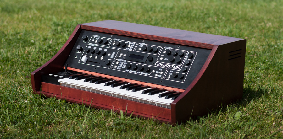
| Graphic of the Effects Section |
There are two effects units which contain the Spin Effects FV-1 module. A wonderful beast with three controls for various parameters. The module allows for eight different effects algorithms. Both of the units contain the same effects given that they are on different signal paths.
The Keyboard
The keyboard is something I salvaged which has a simple diode matrix setup. I've used an Arduino MCU to map this and put out serial data pertaining to the note played. Nothing overly complicated here. The provision for velocity sensitivity is there but I have not implemented this further down the line.
Joystick
The X and Y parameters of the Joystick can be assigned to many of the different parameters of the FloriVoxTron. This assignment also includes a depth controls the percentage of the parameter affected. Below the joystick are three buttons with three LEDs. These are user assignable pre-sets for the joystick which allows the user to quickly change the joysticks destination without wading through the menu of the LCD.
Voices and their Play Modes
 |
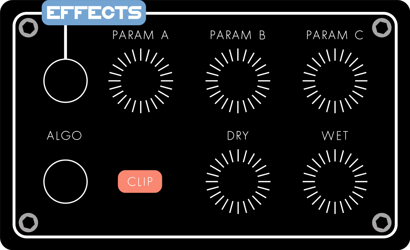
| Graphic of the Voicing Section |
One of the nice features of building your own instrument like this is you can put in any functions you want. How the sample sets are played and mixed was one area I wanted a few special things.
As mentioned before, the FloriVoxTron has four voices which can be assigned four different sample sets. But in fact I have taken this further. Within a patch, each four voices can have five different sample sets. This works simply with each press of a key, the sample set changes. It will only change the sample of the next note played and not any notes currently playing. This can be configured as a sequential process or randomly on the list provided.
Another voicing function which is more about VCAs associated with each voice is the different Play Modes. There are three modes - Stack, Crossfade and Rotor. In Stack mode you simply choose which voices you want to hear by selecting the sample set and the voice activation button. Crossfade mode makes use of the slider below the voice select buttons. Voices can be assigned to the Left or Right side of the fade so the user can manually fade between the left and right where you'll hear the selected sample sets. And finally the Rotor mode where another LFO spins around and cross fades between each of the active voices. This LFO also has a second LFO to give that lovely effect of one LFO controlling the speed of another.
The finally voice related function is the Stutter function. Only voice Eins uses this function due to a hardware limitation. Timers are used to start and stop the playing of a sample activated on the keyboard. As you add more notes via the keyboard the Stutter of the new note is not in sync with the previous. In addition the Scatter control will introduce a random time for the stop and starts of all notes being played. A feature of the voice activation buttons which enhances this process is when you hold a note on the keyboard and turn off the voice, the note is held without the use of the keyboard now so you can go onto playing another voice while this held voice happily plays in the background. The held function works independently on all voices.
The Sample Sets and the Tsunami Sample Player
The sample sets took quite a lot of time. Unlike a traditional sampler, the Tsunami Sample Player doesn't take one sample and transpose it across a keyboard, so for me to make the sample sets means creating a sample for each note. This is not a great problem as I wanted a more natural sound. Most of the sample sets I have used are unique samples per note anyway. The process of recording these samples from their origin was helped by an old program I had laying around named
Chicken Systems Translator which I originally purchased for an old hardware sampler I had. This would make my life easy by playing back a range of notes and recording the audio to individual audio files. From here I would rename them to be placed in the appropriate location on the Tsunami.
The Tsunami uses a micro SD card to store the samples in 44.1khz 16bit stereo format and it can address 4096 of them. They are referenced by simply numbers of 1 to 4096. The Main MCU in the FloriVoxTron does all the work of transcribing the chosen sample set and played notes to the appropriate sample number on the Tsunami. This communication is done via one of the serial connections on the Arduino Mega2560 which is the Main MCU.
I won't go into great detail about the Tsunami as this can be gleaned from the
Robertsonics web site here.
One of the reasons I chose the approach of four difference voice audio paths is because the Tsunami allows for this with its audio outputs. It has eight audio outputs which can be configured as eight mono outputs or four stereo outputs.
A feature of my sample setup is that each of the four voices mentioned - Eins, Zwei, Drei and Vier, can have a one sample set allocated or it can up to five sets. These five sets can be arranged to play randomly on consecutive note presses or in ascending order. Meaning each time you press one note a different sample will play. This allows for some interesting effects especially in the case of say a choir where we have 5 different vowels being sung. As we press notes we get different vowels being sounded.
Hardware
The Front Panel
 |
| Front view of the FloriVoxTron |
The front panel is made from 6mm black acrylic. As with many of my projects, I have routed the channels for the text which I have then filled with white acrylic paint. The LED bezels are opaque acrylic once again routed for their markings and filled with black acrylic paint. Behind the LED bezel is a shroud which concentrates the light from the LED through the bezel and limits the spread of the LED.
 |
| Closeup of the front panel without the case |
The knobs for the rotary encoders are three pieces of acrylic glued together, routed and polished to hide the joins in the acrylic. A shaft has also been cut out on the bottom side. The touch switches are actually drawing pins. This works just fine though they are a little fiddly. In another project where I have used touch switches, I used bolts and small magnets which are more sturdy but do have some contact issues. I have not found the perfect solution to making a durable touch switch contact but I do like using touch switches.
As far as the operation of the rotary encoders are concerned, they have several functions or modes. I have taken advantage of the switch that all the rotary encoders have to make the encoders multifunction. The front panel MCUs will tell the Main MCU several states of the rotary encoders. They will say when it is rotated, pressed, pressed and held and double clicked. I've taken advantage of this to place two functions on each rotary encoder with its current state reflecting in the LCD.
The Front Panel Section
 |
| Cross section of the front panel where the two layers of printed circuit board can be seen |
The front panel is quite complex. Each of the sections laid out have two layers of printed circuit boards behind them. The control of the RGB LEDs comes from the MCU after it's received information from the Main MCU. The MCU also reads the touch switches and rotary encoders and passes this information back to the Main MCU. In some cases I have used two MCUs due to the amount of digital I/O pins needed. Most of the MCUs are Arduino Pro Minis of the 168 variety. In this instance I have used I2C to send data to and from the Main MCU. I2C works well between Arduinos.
Quad DAC Boards
 |
| The rear of the FloriVoxTron without its case. The foot controllers, MIDI, Power Input and Audio Outputs are clearly shown. The SD Cards containing the sample sets and patch data can be seen also. |
As mentioned earlier these are boards which contain a STM32, blue pill, and a quad 8-bit DAC along with support components. They get their commands from the Main MCU via Serial. At the time the STM32 didn't have a very good I2C support so I decided on a protocol that was more appropriate which was the serial as we are not talking about high speed communications here. The output of these boards are used to control the various voltage controlled boards like the VCA and VCF boards. There are eleven Quad DAC boards in the FloriVoxTron.
The Main MCU
This is where all the various input and outputs originate and all control is coordinated. I decided on a Arduino Mega2560 primarily because of the multiple serial ports available. The keyboard interface outputs serial data, the Tsunami Sample Player receives and sends serial data, there's the MIDI port which is serial as well. The Main MCU has a Sd card interface where patch data stored along with sample set control data and of great importance, the parameter data. The FloriVoxTron has almost 500 parameters. The parameter data file on the SD card tells the Main MCU which Quad DAC board to send data based on the parameter being changed. Other data contained in the parameter data file is things like the format of how to display parameters on the LCD and if a parameter is editable via the LCD's menu. The parameter data file is quite large and an SD card seemed the fastest and most convenient format to use. I investigated EEPROM which I have used in other projects but this was much slower plus it had the disadvantage of not being able to easily update unlike an SD card which I can update on my PC. The parameter data file is created from a spreadsheet via a small program which compresses the data down in a format that is easy for the MCU to read.