CNC Router PCB 

It has been a while since I worked on the Therematron synthesizer and one of the reasons for this was I was waiting on some parts for the CNC router that would allow me to create the printed circuit board for the MFOS Adjustable LM317/LM337 1.5A Supply. I forgot to order this board when purchasing the other parts for the Therematron so I reminded myself that I had read somewhere that people use these small CNC machines to create prototype printed circuit boards.

Like most exercises that I attempt, they seem quite simple in concept but end up throwing all sorts of obstacles in my path during the project. The initial reason for purchasing the CNC Router was to create front panels as I've mentioned in my initial Therematron blog. I found an Instructable which takes the reader through one method of creating pcb's (printed circuit boards) using a CNC Router. Here's the page by the way Instructable for PCB prototyping. I've been using veroboard to mount my circuits onto in the past but I've found the boards end up quite large in size which isn't usually a problem but I thought I'd give the CNC pcb a go. Ray Wilson of MFOS had already designed a pcb for this project so I took the low resolution GIF image file and retraced this in Macromedia Freehand. Freehand is a out dated vector graphics program that I have used for years and at the moment I don't have a reason for changing over to anything else even though I do own legit copies of Illustrator and Indesign.

So the approach needed was to retrace the boards tracks and place circle where the drill holes are needed. That was quite easy and took about 20 minutes to do. From the Freehand file I needed to create several files. Firstly, I needed to create the tracks but hold on ! What I really need to create is a file for where I don't want copper on the board. This takes me to another area. To use a CNC you need a control program. I chose Mach3 as most bloggers and forum people suggest this as the most flexible software. Essentially this program takes GCode (most used numerical control programming language) and moves the various axes on your CNC around. But to get the GCode I need another program. My searching ending up with a program called Cut2D byVectric. What this program does is take your vector graphic and allow you to choose the type of cutting you wish to perform and with what cnc drill bits and then creates the Gcode to move the CNC around. OK ?

So with a bit of Freehand vector trickery I created a series of shapes that give me a 1mm gap around the copper tracks on the board, removing the copper blank on the inside of the board but leaving it on the edges outside the tracks. This took a while to work which is annoying in some ways since this will probably be one in few times that I will create pcb's this way. Most boards I will do in the future will come via the pcb design software. So now I have the tracks file but I also need the drill file. Cut2D was quite happy for me to simply have a file which contained the pcb pads as circles which it then used to place drill holes. That was easy but then I remembered I wanted two different drill hole sizes - 0.8mm and 1.7mm, so I need to then create a file for each of the drill sizes with only the pads that represented each hole in two separate files. Not too hard.

So I've mounted down my copper board to the CNC bed, placed the engraving bit into the machine, set the zero points and I'm ready to go. The bit used for the hatching (clearing out large areas) was an engraving bit which is only 0.2mm wide at the tip and this had to clear quite a bit of area. So when it finished it took just under 3 hours. A little slow but the machine did it without any user help. The drill holes were quite quick and were done in a few minutes. So that is a quick rundown of the process - very quick run down. In all it did take a full day to do as I also did a couple of other small boards as tests. But these boards I designed in my pcb design package Diptrace but that is another story for another century.

There are several videos on Youtube showing this process of engraving the printed circuit board so I will not add to the video collection. So just go to youtube and search for "cnc pcb router" and you'll get several.

I'm very happy with the result. Note you can probably see a few erroneous discs on the copper areas to the right. When I first went to cut the board I didn't measure the board size and started the cut to find the other side holes off the pcb so I restarted and just managed to fit it on the spare piece I had. The other small issue here is that the MFOS boards are double sided with just one small link that I will have to put in manually with a jumper wire. Double sided boards are a trick for another day.
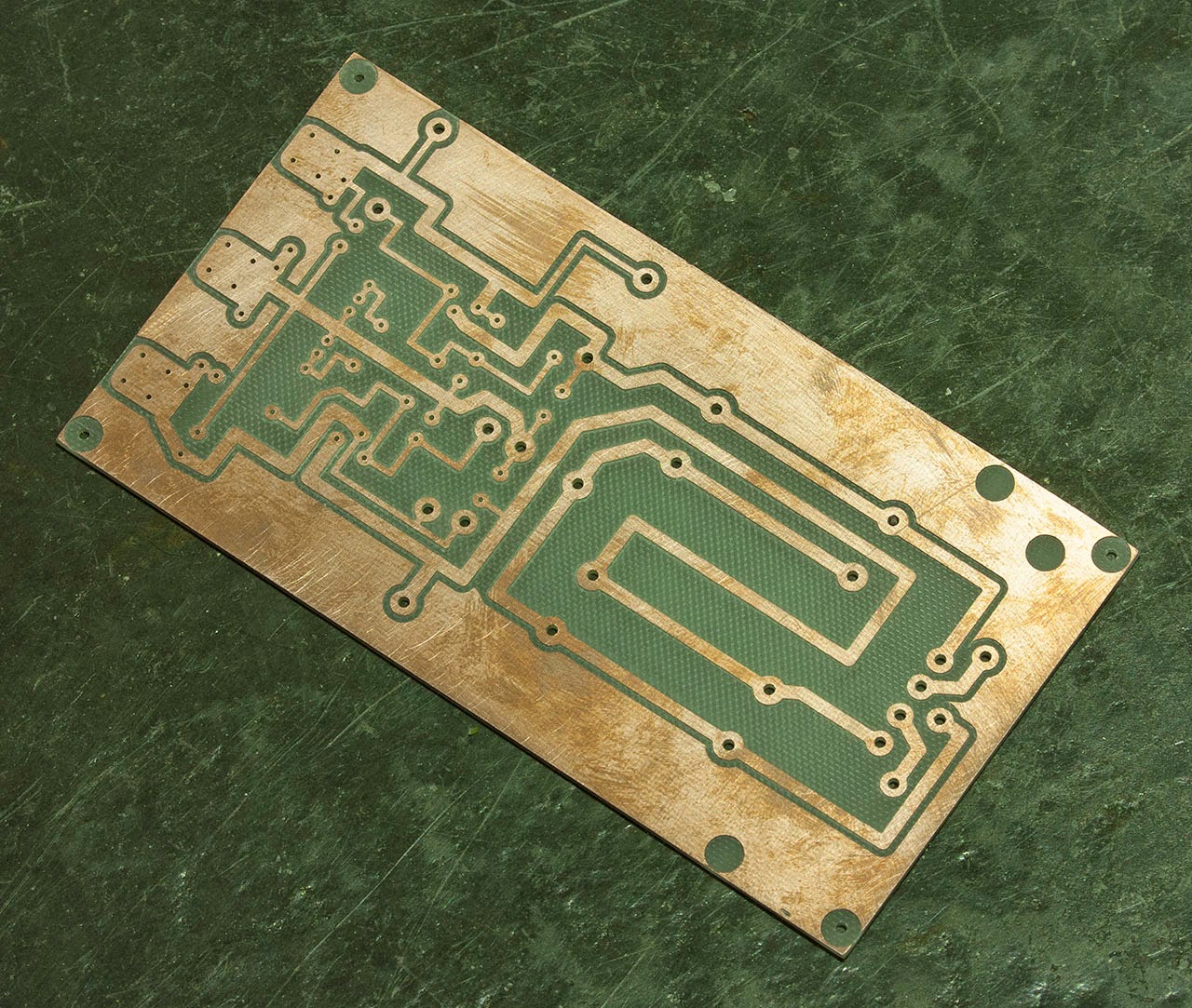
The MFOS PCB with a few mods
Addendum: AGGHHH. It wasn't until I went to populate this board with components did I realise that I failed to reverse the artwork thus it is backwards. Oh well I won't do that again.

Therematron - where the trouble starts ! 

Recently I got together some friends with the intention of creating a Kraftwerk cover band. It's going well but one of the ideas we stressed with regards to performance is that we would use analog gear as much as possible and where possible. Since we started to learn their earlier tracks in particular Radioland I decided that I wanted to make an analog performance synth that didn't use a keyboard but instead used something along the lines of a Theremin.

So I couldn't settle for something as simple as a basic Theremin. So I looked into the problem. PAIA's Theremax seemed a good starting point as it was essentially a basic Theremin with some expand ability added in the form of voltage control and gate outputs.

The PAIA Theremax adds the ability to mix in a more square waveform. To control outboard units, there are Pitch and Volume Control Voltage outputs. But the features that really set Tmax apart as a gestural controller are it's Velocity Control Voltage (proportional to how fast you increase the Volume) and Gate/Trigger outputs. A convenient foot switch input allows muting the internal tone source without disabling the CVs.

So I thought - "This is a controller as much as a sound maker ? I'll add a synth to it !". I've been wanting an excuse to make a MFOS SoundLab Mk2 for sometime. So the addition of the SoundLab Mk2 will give me much more tone making ability and with the Theremax's abilities I can use the Aerials to control more than just pitch. Of course later I can make up a small keyboard for this unit but for the moment to aim is for non-chromatic.

The final piece is Ray's Echo Rockit which will give the whole unit another dimension. The Echo Rockit is a PT2399 chip based echo unit which can be used to create numerous BBD type effects with some "lovely" nasty artifacts to boot.

The whole package is to be built into a wooden box with a two tier front panel which has all the patchbay included.

Here's the front panel design at the moment:-


The case is plywood which will be varnished. The front panels are a composite aluminium material which is a piece of pvc sandwiched between two thin pieces of aluminium. Very easy to work with, light weight and strong.

The front panel design is something new that I have started working with. Using a CNC router, I cut through the aluminium layer and then fill this cutaway area with acrylic paint. Even though I am still in the testing stages of this process it is going quite well. My next test for this process is to spray paint a piece of this material black and then engrave the piece to see if the paint stays in tact. The reason for doing this is that the whole process is going to be more affordable if I can paint the standard white material any colour I want and then fill in the engraved areas any colour I wish. I can purchase coloured board which is my backup process.

Here is the first physical result of the job - the PCB boards are now fully populated with components.


I have come across an addition which will need some fiddling around to achieve but I really need to unit built before I can sort this out ? Oh well I may end up with an extra control or two which eventually don't do anything.

Next step is to make up a wiring diagram I think.

UM16 SLA Battery Charger 


This is the UM16 multiple SLA battery charger that I designed specifically to charge multiple 12v SLA batteries which will be used with my UM12 motion control camera system. These are in the form of three dual 18Ah 12v SLA units.

The UM12 MOCON (updated blog coming soon) requires several voltage rails but the stepper controllers in particular need at least 20vdc. The decision was made to create this via a 24vdc centre tapped arrangement so that I could derive the other voltages ie: 12vdc without excessive loss through voltage regulators. The other power rails are for powering the camera(s) attached to the pan / tilt head of the MOCON.

The reason for choosing SLA (Sealed Lead Acid) batteries are simply that they are the most affordable option of rechargeable battery that I could find taking voltage and power into account. Their downside are that they take quite a long time to charge and that they are heavy. These downsides are what lead to this project being designed.

What is contained in the UM16

The UM16 contains two 4 stage battery fighter 12v SLA chargers controlled by a Arduino Uno. The Uno monitors the state of the connected batteries and manages the switching via a relay bank to allow for automatic charging of up to 5 batteries. I chose to use prebuilt charger units because I could not find kits or schematics that would make the job easier plus I already had one of these units that I had previously been using.

The aim of the project was to create a battery charging management system plus trying my hand at :-
  • using a boot loaded Atmega 328 chip as opposed to an Arduino prototyping board
  • investigate the 75HC595 shift register for controlling a bank of 16 relays
  • Use a set of 4N25 opto isolators to interface with the Battery Fighter charger units
  • Understand and implement a TLC5940 - a 16 channel PWM unit to control RGB leds

The schematics were design in TinyCAD and these were translated to VeeCAD for the veroboards.

The Battery Fighter chargers

The Battery Fighter chargers have several leds that show the varying state of the charger :-
  • No Battery
  • Wrong Polarity
  • Alert - meaning a dead battery
  • Bulk Charge
  • Absorption
  • Maintenance

4 stages Charge algorithm by steps
  1. Qualification: Ensure the battery in good condition prior to charge. Charge will not be started if battery is less than 2.0V.
  2. Bulk charge: The normal charge is commenced to deliver the constant current for charging up the battery until 80% full.
  3. Absorption charge: The charge program has switched over to Constant voltage; the charge current has to be reduced according to the raised of battery level, until the battery is full.
  4. Maintenance: The battery can be permanently maintained at a proper work level and to be kept ready to go.

The Arduino Code
My code is quite simple. The program changes the relays to attach Battery One to charger A and Battery Two to charger B. Here it reads and stores the state of those batteries. These states are read into the Arduino via the 4N25 opto isolators which are attached to the chargers leds. These states are read in via a resistor ladder on an analog input on the Arduino. This helps cut down on wiring and connections to the Arduino. The software sits for a couple of seconds on each battery to get a proper reading and then advances charger A to battery 3 and charger B to battery 4 and finally repeating the procedure to battery 5.

Once all the batteries states are recorded the chargers start from the top down and takes the charge of each battery until they are at Maintenance stage. Of course if a connected battery was already in Maintenance stage this would be ignored during the charging state. Once all the batteries are at Maintenance stage the unit goes into a sleep mode.

I did originally plan for the chargers to take all the batteries that needed the most work to the next level first but I decided that this was not necessarily good for the battery and the approach of taking a pair of batteries at a time to full charge was a better approach for the longevity of the battery.

A small addition is a thermistor, device for converting temperature into resistance, inside to turn on a small fan for ventilation one the transformers warm up during the bulk charge state. Admittedly these do not get that hot when in bulk charge mode. The reason for doing this is that the original Battery Charger units did get quite hot although they were in a small case.

The connections I've chose to use are a 4 pin microphone type which is not a standard for power but I decided a while back that these connectors are durable and can carry the power I will be using. The UM12 uses a 3 pin version to carry the 24vdc centre tapped.

Conclusion
In the end the unit works very well. I did have a couple of setbacks during the construction. I shorted 12vdc across the processor which took it out along with it's USB FDTI connector. For some reason one of the charger units was also damaged during construction. This took a while to find as it would consistently give me a Maintenance reading for batteries even when a battery was not connected. I originally thought this was my programming or one of the relays at fault. The unit is built inside a Pelican style case which makes for protected storage during transport. The front panel and base plate are made from Signbond composite panel which is an excellent material for these projects as it is quite light and rigid but easy to work with. You could easily argue that this is an overly complicated unit especially when you look at the insides. I could have probably found a smaller solution to the routing of the charger and battery connections probably via transistors but these ready made units made the process simple.

In depth reasons why I chose Seal Lead Acid batteries.

The UM12 system uses an average of 24vdc at 1A during a timelapse sequence. The price of SLA batteries is quite cheap versus some of the more recently available battery options like LiPo (lithium polymer). The trade off with SLA batteries is their weight and their slow charging rate. The weight of the a SLA is about 300grams per amp hour (based on an 18Ah battery) whereas a LiPo is about 100g per amp hour (based on random unit found on ebay). So, a dual 18Ah battery weighs in at about 11kg whereas an equivalent LiPo would be 3.5Kg. So a reasonable weight difference. On the other hand the LiPo batteries are much more expensive. The cost of two 18Ah 12v SLA batteries is about $110 whereas an equivalent LiPo set of batteries would range between $400 and $600 depending on the type of LiPo. LiPo batteries vary in price based on their speed of charge and discharge.  Charging a LiPo is also very quick compared to a SLA but this depends on the type of LiPo. So bottom line is that money was the reason for choosing SLA batteries. To configure LiPo batteries to deliver 20vdc at 18Ah would require several individual battery units which would also make the UM16 ridiculously complicated.

UM14 - Arduino based Step Sequencer 

While making the SBE2 unit I realised that a great addition would be a step sequencer. So my definition of what I would like in such a unit started.

The UM14 is made to work with the SBE2 in mind. It has 4 independent 16 step sequence channels which can be linked together. Unlike most sequencers the output control voltage for each channel is limited to 3 voltages. These 3 voltages are still variable across the full CV range though. The reason behind this is that the sequencer is made for the SBE2 which is not a chromatically tuned machine.

I decided to make the brain inside the unit an Arduino since I have a better grasp of computer based circuits than an analog based one. This also allows for greater flexibility in operation later if needed.

Here's my definition of what it will initially do:


Here is the new definition:-


This is a CV and gate sequencer which has 4 independent channels to control the SBE2 synthesizer. The unit is not meant for 1v/oct units and only has 3 CV options per sequencer per channel. The front panel contains two sections - one is the sequence running controls and the other is where the steps of each sequence are controlled.

The step sequence section comprises a matrix of leds which is 4 high and 16 wide. There are three data encoders per row of buttons which set the three control voltage output options. The rows represent the individual sequences whereas the verticals represent the steps of the sequences. The leds will glow a colour relating to which of the three control voltages they output and whether their step will trigger the output or not.

The function of the RGB led is this. It will glow WHITE when its step is being played. When not being played it glow either RED, GREEN or  BLUE which is related to which of the three control voltages it will output when it is played. Whether a step has a triggered output or not will identified by the step led being brighter whereas a non-triggered output will be dim. The momentary button at the bottom of the step column will cycle through all the options as follows:- RED, RED triggered, GREEN, GREEN triggered, BLUE and BLUE triggered. To select to affect you must first press the select button to the right hand side of the row of leds.

The three control voltage knobs as mentioned are data encoders which unlike potentiometers are relative and not absolute. Using these allows for more options with regards to the computer for what range they may address.

To the left of each row of sequence leds are a knob, a pushbutton and led. The button is named SELECT. The SELECT button has several functions. The functions of this section are changed by pressing the SELECT button.

State 1:-
Led is YELLOW. This mode simply selects this Sequence to which the step buttons at the bottom of the columns will act on when selected.
State 2:-
Led is WHITE. This is the sequence length mode. This indicates that the SELECT data entry knob will change the length of this sequence between 2 to 16 steps. The Step  leds will glow WHITE starting from the left hand side and up to the step where the loop will start as of the next step.
State 3:-
Led is PURPLE. Now the data entry knob becomes a sequence DIVISOR. Now the step leds indicate the clock divisor. If only step 1 is lit then the divisor is 1 and if up to step leds 6 are glowing then the divisor is 6. This will allow up to 16 divisions to occur meaning that the master clock has to click over 16 times before the steps will change to the next one.
State 4:-
Led is ORANGE (or something similar). Now the data entry controls the step length of each individual step within the sequence. This represents the number of clock steps the currently selected step will stay for. In this mode the user selects the step by pressing the button at the base of the column of the step and by changing the VALUE control. This will increase or decrease the length. The length is represented by the 8 vertical leds on the left hand side of the panel and can range from 1 clock tick to 8 clock ticks.
State 5 - 7:-
Led is either RED, GREEN or BLUE. Now we are in set the CONTROL VOLTAGE modes. Here we set the output control voltage for 1 of the 3 options for this sequences steps. The led colour is related to that which can be selected on each step. By changing the VALUE control we change the output voltage for one of the three.
State 8:-
Led is PINK. Something that Catgirl synth man has on his sequencer is an option whereby if adjacent steps are on then the pulse is not reset so here would could have a case where normally a step pulse is half the length of the step and turn this option on and the pulse is only turned off when an off step is encountered.


We may change the order and colour of these options once the unit is in operation and accordingly with the ease of use.

The Clock knob will be a pot which controls the master clock rate. This master clock controls all four sequences unless an external clock pulse has been plugged into external clock inputs two to four. Clock input one is considered the master unless others are plugged into two to four as mentioned. I'm not currently sure how I would program this so it might not be available in the final project. There will also be a CV Clock input which is where a Control Voltage can be inputted that will control the speed of the MASTER clock based on a voltage.

On the left hand side is also the memory banks. Here will be 8 sets of memory buttons which represents 8 sets of the 4 banks of sequences plus all sequence based settings. Next to these will be a load and save button. To load a bank you simply press the load button which should make the leds above the bank buttons light up. Press the bank button to load the bank. They will light Green for a bank without a sequence and light Red for a bank with a sequence. If you load a bank without a sequence stored in the memory location then it will load a blank sequence. The same goes for saving a bank.

Three buttons sit to the far side of the sequence panel. As you can see they appear to link the sequences together which they do. When they are selected and the led is glowing then this means that the sequence above and below are linked which means that Sequence 1 now runs for 32 steps. And this will also continue on if the switch between Seq 2 and 3 and 4 is switched on. This example would make a 64 step sequence. The CV and Trigger outputs for the each sequence would then duplicate. So if Seq 1 and 2 were linked then the outputs of Seq 1 and 2 would be the same.

The RANDOM button will randomise Control Voltages, Step Length and Clock Divisor. These will affect the Sequence row that is currently selected. We could put in a UNDO button here as well.

There's a CV input which can control the speed of the sequence based on a CV. Some interesting effects could be generated by directing an LFO output to this input.

At this stage I'll plan to have more plugs on the input and output than needed in case I wish to add another function. This goes for control buttons. That way I will only need to change the labelling on the front panel.

Physical Connections: 8 input plugs which can be used for trigger pulses, control voltages whatever and 8 outputs which will be 4 triggers and 4 control voltages which relate to the 4 sequencers. I'll also put a MIDI IN and OUT which will possibly be another computer that will be both for timing to and from another sequencer and for triggering though I'm not sure I would assign the CV value - hmm actually that would be automatic as these would range across the normal MIDI note value. As I said this would be a third party board that takes care of these things.


Here's a picture of the current front panel design


Sound Box Effets 2 - Project Completed 

I'm happy to now announce that the Sound Box Effets 2 is finished.

About 3 months ago I came across a problem where the Music From Outer Space SVF boards were not operating as I expected them to. They were both operating the same so I came to the conclusion that I didn't like their sound. Not being knowledgeable enough to make changes to the circuit I decide to replace them. So I now needed to find a replacement which used the same controls and jacks as the front panel was completed. The answer was literally staring me in the face - I already had a PAIA VCF module which has exactly the same controls.

Last month I purchased the kit from Scott and built this up last week. The unit almost functioned correctly on first power up once I realised the signal and power grounds needed to be connected together for my purpose.I had a couple of pots backwards as well but that was soon fixed. Oddly though the first VCF has a greater reaction to control voltages than the second but I am not concerned with this. I could probably spend a few days trying to hunt the issue down.

So it's now complete and sounds great. But you know I now realise it's failings but that was going to happen. But that's another story.

The next story - The UM14 - Arduino based Step Sequencer

The wiring stage 

Here is the front panel wiring almost complete. The only missing parts are the four led chaser circuits that sit where the sequence of holes are placed at the top of the panel.