UM12 Motion Control Hand Controller - Version D 

UM12vD Mocon Hand Controller
The Hardware

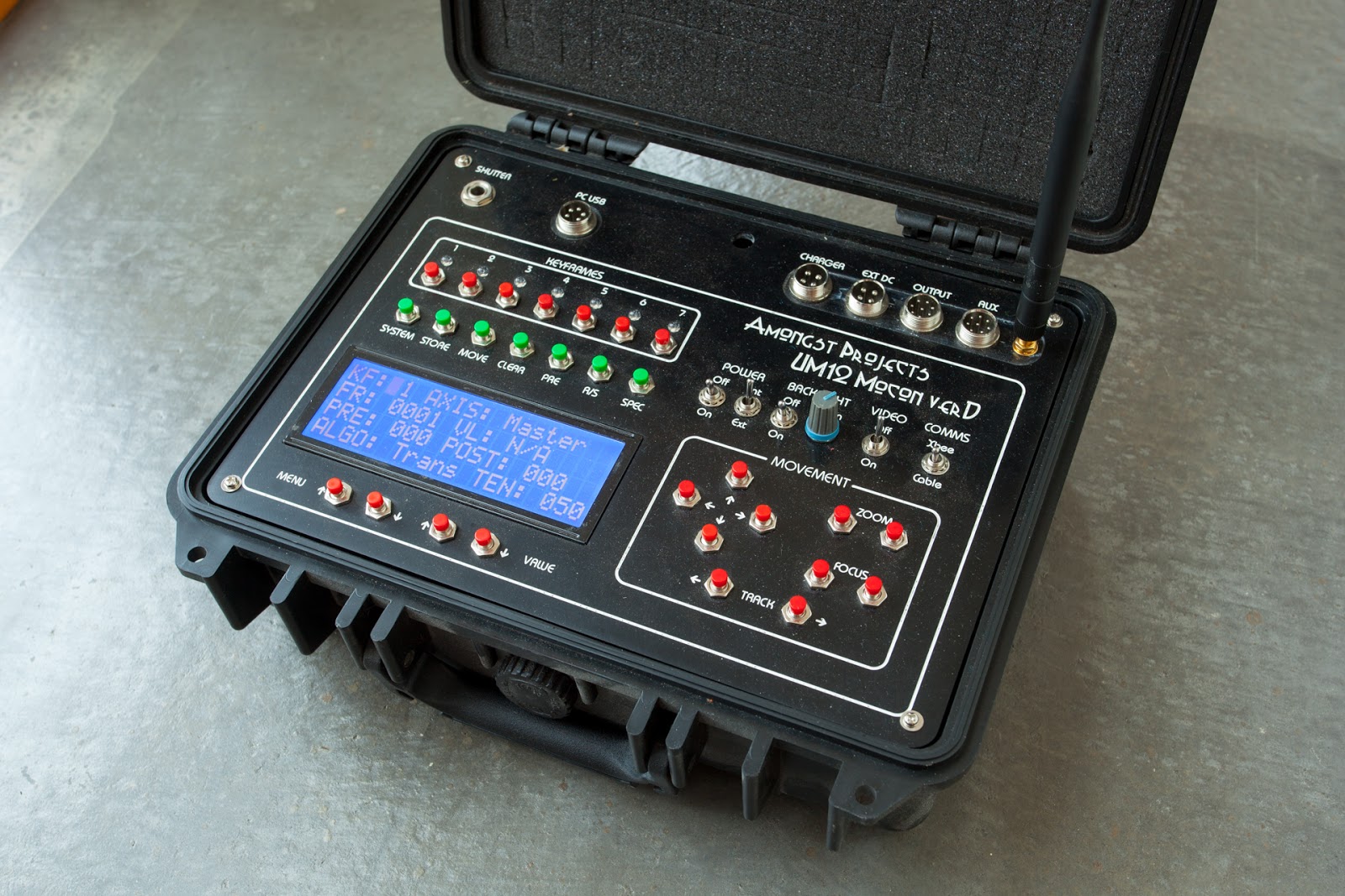
The UM12 hand controller is based around an Arduino Mega2560 processor. The Mega2560 uses the larger Atmega 2560 which has more RAM and digital inputs and outputs to name just a few.

The various pushbuttons are simply read via individual digital inputs with hardware debounce by using a 100nF greencap and 10k resistor on each button.

The display is 20x4 large display which is connected to the Atmega2560 in 4 bit parallel mode.

The leds are RGB leds controlled via two TLC5940 PWM multiplexor chips. This helped reduce the outputs needed to control these lamps plus gave greater control over intensity. The TLC5940 connects to the processor using 4 data pins.

The hardware update from version C of this unit was:-
  • Multiple vero boards replaced with two cnc routed printed circuit boards
  • Removal of video monitor unit into it's own case

I've used some EEPROM to store shots into a small memory bank. The EEPROM is not affected by power removal. You can store 7 shots simply because there are 7 keyframe buttons for an simple control interface. I have written three PC based transfer programs to allow for uploading and downloading of shots for longer term storage along with a small program which can display the curves of each axis.

The communications between the Hand Controller and Master Controller (dolly) is via a Xbee 1mW transceiver with external aerials. This was the most affordable at the time I started this project. I would now look at Bluetooth.

There is shutter controller hardware on this unit but the software is not implemented to use it.

Hand Controller Software

The purpose of this unit is to control the initial movements of the UM11 dolly and create keyframes for movement points. No movement calculations are done on the Hand Controller but are calculated on the Master Controller. The master controller's processor is a ChipKit Max32. This was chosen because of it's large SRAM memory and also processor speed which is 80Mhz. Again, if I had my time again and started this project now I would simply go for something a Raspberry Pi or Arduino Due.

The unit can have up to 7 positions on each of the 7 axes.

These axes are:
  • Track
  • Pan
  • Tilt
  • Focus
  • Zoom
  • Interval
  • Exposure

There is also another control axis called Master which is a easy way of storing data in all the axes at one press of a button.

The start and end keyframes of 1 and 7 are a given value. The shot needs to start somewhere and end somewhere. These keyframes will be set to the minimum frame of 1 and the maximum frame of Total Frame Count. Each keyframe for each axes has several parameters. These parameters are:-
  • Frame
  • Position
  • Pre Hold
  • Post Hold
  • Transition Type
  • Tension

Frame is the frame number at which is axis keyframe information will take place.

Position is a value which is relevant to the axis type. All the motor values are relative to the home position and can range from -65000 to 65000 again depending on the axis. The home position is also a relative value as the dolly has no absolute values of position. The Interval andExposure axes are not motor axes so their Position values are different. The Interval axis ranges in seconds from 3 seconds up to 5 minutes and the Exposureaxis ranges from 1/30 of a second up to 30 seconds in steps the same as 1/3 stop steps within a camera.

The PreHold value is a value in frames for which this keyframe position will be held before the Frame. Likewise, the Post Hold value is the number of frames that this position will be held after the Frame. Keyframe 1 doesn't have a PreHold and Keyframe 7 doesn't have a Post Hold.

Transition type if what type of move will be performed from this keyframe to the next active keyframe.
The options are:-
  • Transition
  • Smooth
  • SmoothB

Transition is a default and useful curve. By default without any post hold frames it will be linear. Whereas if you place a post hold then the following curve will have an ease out applied to it. Should you want to create a keyframe where the camera must pass through on it's way between two other keyframes then you choose the Transition type for a smooth transition.

Smooth and SmoothBare quite similar to the Transition type and provide a nice smooth start and end to a move. The difference between the two is in the Tension value and how this is applied. With Smooth the tension value represents a point placed at a percentage between the two points whereas SmoothB is simply a number of frames from the current keyframe for this imaginary transition point.

The curve calculations are Catmull Rom and the three options above all use the same calculations for their curves. For intensive purposes you could happily use the Transition type for all moves but the SmoothB in particular lets you do some more technical moves that may help with getting around issues of an natural move. To some degree this is an experimental option.

Finally the Tensionvalue, which has really been explained above, essentially sets the position in frames from the current frame for where this imaginary transition point exists. So unlike using Bezier curves which have 2 dimensional handles for each point, the Catmull Rom is simply a curve system whereby a line moves smoothly through a point. From my perspective the Catmull Rom system is easier for the more simple shots that a timelapse photography rig would use. The other issue with using Bezier curves is the limited text display wouldn't give any useful feedback. I believe Bezier Curves really need a display which can show the line being produced.

The System Control pushbuttons

There are seven function buttons underneath keyframe buttons. Working from the left to the right.

These are:-
  • System
  • Store
  • Move
  • Clear
  • Pre
  • R/S
  • Spec

The System button changes the mode of the unit between the Keyframe Menu and the System Menu. The System Menu is where system and shot based parameters are set.

Following are the current System Menu items:-
  • Shot Store
  • Total Frames
  • Frame Split
  • Shot Direction
  • Shot Pre Delay
  • Sub Frame Start
  • Sub Frame End
  • Screen Saver
  • Frame Rate
  • Shot Type
  • Park rig at end
  • Axis Limits
  • Preview Video
  • LED intensity
  • Frame Increment
  • Hold Increment
  • Slice Count
  • Motor Delay
  • Track Engage
  • Pan Engage
  • Tilt Engage
  • Focus Engage
  • Zoom Engage
  • Buzzer Enable
  • Track Simu
  • Safe Move
  • Axis Key Jump
  • Move To Home
  • Set Home Pos

Shot Store - This has it's own sub menu. This is where the user can Store, Load, Clear, Send To PC and Receive From PC any shots stored in the 7 memory locations. Using the Value keys to scroll through these options and then select one of the 7 Keyframe buttons to complete the operation.  The exception here is the PC transfer options which just rely on any of the keyframes buttons to be pressed because these PC transfer functions will send or receive all 7 locations. The keyframe leds will display as Red to show an empty memory location and Green for a stored shot.

Total Frames - This is the total number of frame for the current shot. This is limited to 4000 frames which is due to the size of the SRAM on the ChipKit Max32 processor within the Master Controller.

Frame Split - This is a useful function which will automatically assign a Frame number to a Keyframe when you Store the values of the Keyframe. If this is turned on then the Frame number assigned to a keyframe will be in the middle of the previous and next keyframe. For example if you have 1500 frames in the shot. KF1 will be at 1 and KF7 will be at 1500. If you store any keyframe at this stage it will be assigned 750. And if you keep going and store a keyframe between that previous keyframe and kf7 then it will be stored for frame 1125. If this function is OFF then you will need to enter a Frame number manually. You have to pay close attention to this because by default it will store it at Frame 1 and I cannot predict what the system will do if you have two keyframes on the same Frame ???

Shot Direction - Simply has two options of Forward and Reverse. If Forward then the shot will run from frame 1 to 1500 using the example above and if set the Reverse then it will run from Frame 1500 to 1. Note that in reality it will run from the values set in Sub Frame Start and Sub Frame End.

Shot Pre Delay - This is a delay seconds before the timelapse shot starts running.

Sub Frame Start - This is the actually frame from which a timelapse will start from. This is useful if you are shooting a long shot in multiple sections where each section is at a different time of day.

Sub Frame End - As above but for the end frame number.

Screensaver - This switch will turn the screensaver off and on. It turns off the backlight on the LCD display after 5 seconds. This function is a legacy from when the unit also powered the video monitor and I tried everything to lower the drain on the inadequate battery. I leave this off mostly.

FrameRate - This is the framerate at which the realtime preview will run. It has a valid range from 1 to 60 frames per second.

Shot Type - The value has three options - SMS meaning Stop Move Stop which is the default timelapse mode, Stop Frame which is linked to the use of a push button on the Aux input on the Hand Controller and will move one frame and wait until the button is pressed before doing the next frame and Continuous which is a experimental mode utilising the real time preview where the frame is exposed moving at speed it would during a video type move. The amount of wobbly in the system really does make this unusable but could be tried on a fast shot to add blur.

Park Rig At End - Simply a function to return the dolly to the home position and point the lens down.

Axis Limits - This will limit the movement of all motor axes to those set within the software.

Preview Video - This enables the use of the Magic Lantern firmware within the Canon 5D Mk2 camera to turn the recording of video off and on during a shot preview. The function controls the half shutter connection which the Magic Lantern firmware interprets as a control for video recording.

LED Intensity - This sets the backlight of the LCD and the RGB Leds. There are 4 options - Bright, Normal, Dim, Dark - which range from full intensity down to dark night intensity. 

Frame Increment - This is a value which sets the increment value of user input values with the keyframe displays and it ranges from 1 to 100

Hold Increment - This is similar to Frame Increment but is specific to the values of Pre and Post Hold

Slice Count and Motor Delay - are system level values which adjust the speed at which the Realtime Preview runs at. The Slice Count is the number of slices per second the motor moves and the Motor Delay is a very small delay in milliseconds between motor steps. These could be used to great use for doing realtime moves for video to slow and smooth shots. The realtime preview is not perfect but works quite well to give an idea of what your shot will look like when finally composited into a video.

Track etc Engage - This turns the axis off or on. The motor will be engaged but will not move.

Track Simul - This is Track Simultaneously. I've found that moving all axes at once does introduce stutter in the track so I've added this option to move the track separately to the other axes when the rig moves. Turn this on and the Track will move with the other axes. Turn it Off and all moves will start with the Track and once the Track is at it's destination, the other axes will move.

Safe Move - When Safe Move is turn ON the Pan axis will move to it's home position first and then once the other axes has arrived at their destination the Pan will move to it's destination. I found this to be a useful function when filming close up objects and avoids the edges of the Pan assembly hitting objects.

Axis Key Jump - This OFF and ON function related to user inputting of information within the Keyframe Menu. With this function turned ON, the keyframe display will change to the Axis that you move with the arrow keys. With this Function OFF the keyframe display will not change.

Move To Home - By selecting this value to ON the rig will move to it's programmed Home Position

Set Home Pos - By selecting this value to ON the current location of all the Axes will be set as the value 0 or Home Position.

So that is all the current System Menu items within the Menu items but there are a couple of other features which will be run if you select Function buttons while in the System Menu.

To move around the Keyframe screen you use the Menu Up and Menu Down buttons and to change the select value you use the Value Up and Value Down buttons.

If you press the SPEC button the Hand controller will request the current shot data from the Master Controller. This function is mostly used when you have turned off the Hand Controller or a bug has caused a freeze within the Hand Controller. If you press the STOREbutton while in the System Menu you will display the Real Time Clocks Time and Date as well as the current voltage of the interval battery.

Back to the other Function buttons. The Store button is used to Store current axis positions into the selected Keyframe number. The only value that actually gets stored is the Axis position and Frame number. The Frame number will be 1 if the Frame Splitis OFF and it will be the middle Frame value if Frame Split is ON.

The next button to the right is the MOVE button. The button has two functions. The first press will give you the option to Move the rig to any active Keyframe of any Axis. You need to have selected the Axis you want first by using the Menu and Value buttons before pressing the Move button. Once this is pressed the rig will do a calculation and then move all axes to that position. The Track Simul and Safe Move system values will affect how this move is performed.

The second function of the MOVE button is to move the whole rig to a specific Frame number. This is a useful function to find where the rig will be at any time during the shot. The Value Up and Value Down buttons will change the Move To Frame and once you have chosen the Frame you wish to move to you hit the MOVE Function key again. If you wish to cancel out of this function then you hit theSPEC button.

Moving along, the CLEAR function key simply will clear the contents of any Keyframe. There is a small bug within the system whereby if you have created a keyframe using the MASTERaxis then you cannot delete a keyframe. Yes it is a problem but personally I've just worked my way around the issue. I find that the best way of using the MASTER axis is mostly for KF1 and KF7 and from there on I will only use the individual Keyframes within an Axis. Often this is the case where you want the TRACK to move at a constant pace and the PAN and TILT to do their thing. A common basic move for timelapse.

The PRE key is Preview. The is the function to do a realtime preview of the timelapse shot. Simply pressing the PRE key will initiate the preview. The first step is to see if the rig can move at the speed requested. There is a maximum speed limit on the rig. The rig can go faster but will have less fine movement. This is something that has to be set within the dolly case and has been set at an optimum already for timelapse. But the controller will either start moving to the beginning of the preview if all is OK or return with an error if it is too fast. I find that if it can't do the preview move then the rig is probably moving too fast anyway. The Hand Controller will then ask you to press the PRE button again to start the actual preview movement.  You can cancel a Preview during it's run by pressing the Preview key again.

R/S is Run and Stop. This is where you will start the timelapse shot running. Pressing the key the first time will move the rig to the start of the shot. Remembering the actual start of the shot is what is defined in the Sub Start Frame or the Sub End Frame depending on what direction the shot is running is based on the Shot Direction value set in the System Menu. Once a shot has started it can be stopped by hitting this button again. It may take a couple of hits but be patient as it will not register the Stop until it has completed the current frame exposure and movement. But hitting the key several times isn't a real issue.

By pressing the SPEC key while in the Keyframe Menu will put you into a special time calculation function screen. The idea behind this function is to allow you to calculate when to start the shot running if you want the rig to be in a certain position at a certain Frame number. Use the Value Up and Value Down buttons to change the Frame number. The Frame Number will start from the where the rig is currently located. The Time Start value will be the current time that you entered this screen. You can change the Hours value by pressing KF1 to increase and KF2 to decrease, change the Minutes value by pressing KF3 to increase and KF4 to decrease the value and finally using KF5 to increase the Seconds and KF6 to decrease the Seconds. The calculation should be immediate but are done on the Master controller so you can't do it without the Master controller being active.

Just a note on the RGB leds above the Keyframe Buttons. During the Keyframe Menu mode these reflect whether the associated Keyframe has a store value. If the Keyframe Display is showing Master then the keyframe leds will be Green whereas if the keyframe display is showing a specific axis it will display active keyframes as Blue.

The other front panel controls include the Axis movement controls at the bottom right of the front panel. This is where you move the various axes in the chosen direction. Simple !.

Above the axis movement keys we have power switching mostly. Starting on the left is the Main Power button followed by the Internal and External power input. When set to Internal the internal battery will power the unit and when set to External the power will be taken from the Ext DC socket at the top of the panel. This socket is wired in my standard 12v 4 pin plug configuration which is positive on the bottom and negative at the top. Next is the LCD backlight controls. The Off and On switch controls the power to the backlight and the Intensity controls the Contrast which is adjusted depending on the angle or viewing. The Video Off and On switch is no longer used as this unit was constructed before I moved the video monitor to it's own case. The Comms switch changes how the Hand controller talks to the Master controller. Should the wireless communications fail for whatever reason, a cable can be connected from 8 pin socket at the top of the panel named Output to the similar connector on the Dolly named Comms.

Running along the top are various sockets. Starting from the left is the Shutter connector. This is a 6.5mm or 1/4" stereo socket. This is wired for half and full shutter connection. This is not current used by the software. It was installed just in case I wanted it for the future. PC USB is the connection from the Arduino Mega2560 for programming purposes and has no use during operations. Charger is for connecting the UM16 SLA Battery Charger to charge to internal sealed lead acid battery. Ext DC is for connecting an external 12v dc power supply should the internal battery become flat. Note that current software will complain the battery is flat but will not turn of the machine off. Output is a for connecting the Hand Controller to the Master Controller via a cable should the wireless connection not work. Aux is currently only used with the Push Button controller for stop motion timelapse but also contains other inputs and outputs connected directly to the processor for possible other future enhancements. And finally the Xbeeconnector is for the aerial to increase the radio transceivers signal for the two way communications between the Master Controller.
  • Share

UM27-LCU - Lighting control units 

UM27-LCU - Overall View
UM27-LCU - close view of controls


These unit are designed to control two light units. One is a standard 5v USB type light and the other is a specifically modified 60 led unit. The two units are essentially identical thought the self contained unit has it's own 9Ah SLA battery and protection electronics.

These simple unit uses pulse width modulation derived directly from the Arduino Nano processor and controls two current limited led drivers to control the intensity of the connected lights.

The smaller unit has a 4 pin 12v dc input which gets it's power from the Video Monitor unit which has a 9Ah battery or from one of the UM19 battery units when using a small adaptor cable. The unit is capable of running from 10 to 30vdc on it's input thanks to the use of buck converters on the power line.

As part of making this unit I wanted to try using both an organic light emitting diode display and also a rotary encoder for data entry. The rotary encoder has both a switch when pressed and also contains a RGB led in it's shaft. A little over kill but great to try out.

The OLED display is quite simply connected via the I2C connection of the Arduino making a total of 4 connections with 5vdc and ground. Several libraries exist for the Arduino to control these types of 128x64 pixel OLED displays. The rotary encoder was slightly more complicated because I didn't want to use an interrupt based method of reading the clicks. I simply used a polling method as I was not concerned with missing steps. I removed the indent part of the hardware to produce a smooth motion. My concern with using interrupts was that I would upset the display of the OLED which is not a simply process.

The lights are simply controlled using two PWM outputs from the Arduino going to two Led driver boards which have PWM control inputs. The intensity of the lights doesn't work out to be linear but I don't really care about this as I simply wanted a method of controlling the lamp from totally off up to totally on. As long as they were consistent in intensity which they are.

The rotary encoder changes the light intensity when rotated clockwise or counter clockwise. The range is 0 to 100 with 0 being off and 100 being fully on. The value will loop around should you go past the lowest and highest values. This seemed a good method of quickly going from highest and lowest values as the speed of which the values change is not fast mainly due to how slow the OLED display is at being written. The display turns off when no data has been changed for a couple of seconds. You don't want an extra glow caused by the display in your timelapse shot.

Pressing on the push button, which is part of the rotary encoders shaft, will change the current lamp to the other lamp and successive presses will alternate back and forward between the two output options.

One of my challenges for the small unit really came in the form of the case and in particular the mount for the OLED. It was a great challenge for me and the cnc router. As you can see the OLED has a black surround. This is a piece of 4mm acrylic which was machined on the rear to have the correct mount holes and display cutout for the OLED display. This display was then hot glued into place. This assembly was this simply placed into a similar sized hole in the ABS case front plate. I could have gone one step further which was to make a clear lens to sit in front of the display as it currently open to the air.


As you can see here there are two units. The small ABS cased unit is the externally powered unit or UM27vB and the larger black cased unit is the UM27vA. They operate in identically the same way. The self contained unit has an extra DC output and internally has all the necessary hardware and software to manage the sealed lead acid battery. The electronics take up less than half the space in the case as the remaining space was created to store the other light control unit along with all the lamps and cables. 

UM25-RFVM - Video Monitor 


This is my Video Monitor for monitoring the video output of my Canon 5D mk2 DSLR.

It's a cheap LCD display which has an old style composite video input. This was originally inside the UM12 motion control controller unit. Things changed when I realised I couldn't power the controller and the video display / rf receiver combo on the 2.2Ah 12v battery within the one unit for long enough. So I decided to split them as separate units.

So the video monitor and rf receiver now live in a case the same size as the UM12 hand controller. This has the added advantage of having space for it's own 9Ah 12v battery which is amble power for this unit plus it can also supply power for lighting units when not being used or any other 12v needs.

The insides are quite simple. I have put in one of the 555 timer based battery protection units which simply monitors the voltage and when a threshold has been hit the relay kicks out, turning off the power.

I've also recently purchased a monitor light box which limits the amount of light hitting this cheap monitors screen.

UM28-CTH - Camera Telescope and Heater Controller 

This unit was planned after I found myself on a timelapse trip where I needed to power a camera beyond the life of a standard camera battery and I wasn't using the UM12 motion control unit. The UM12 motion control rig has a converter to power the cameras but I didn't have a separate unit. I ending up having to drag the dolly out and simply use it to supply the 8v to the camera. A little cumbersome.

So I started out with a plan for a unit which could supply the needed conversion from the UM19 24vdc sealed lead acid battery unit to the 8v dc the Canon camera(s) needed. Then I thought "well while you're making a unit to power the camera why don't you include the other elements that you are likely to need in this situation. "

When I do timelapse during the day I tend to use the standard camera batteries if they are charged and available along with a intervalometer that runs off 2 AA batteries. So I thought why not put a small microprocessor in along with a small OLED display and arrange this to be an intervalometer for the camera. That would get rid of the need for extra non-rechargable batteries and the intervalometer unit. So I've added my shutter control output circuit from the UM12 motiona control unit which is a stereo 6.5mm output jack.

While on the intervalometer subject I do have Magic Lantern firmware on a chip for my Canon 5D mark 2 which I have mainly used to do Raw video but on the last trip I thought I'd give the inbuilt intervalometer a go and it failed several times so I am not willing to take the risk in future.

When doing winter night time star timelapse I would often, if not always, use a heater strap to keep the lens clear of dew. So I'll place a heater controller into the unit. But while thinking about this unit I realised I had another similar unit down my list which is for my telescope. I do astrophotography with my telescopes. So this also needs to have heaters on it so the decision was to have two heater element outlets. Easy !

Before I started designing the schematic for this unit I was reminded of the ULN2803A darlington chip. This chip has 8 darlington transistor pairs which are rated at 500mA each. This would make the unit quite compact over discrete transistors being used. So with this in mind I thought about what else could be controlled by this unit. Firstly, there is the reticle for my telescope. This is an eyepiece that is used for the alignment of stars when doing tracking. It has a target on it lit by a small red led. The ability to control the intensity led will help when faced with different intensity target stars.  I'll add an output for this. The other controllable item that I thought of was for the red lighting unit I have had kicking around that I could use to light my telescope work area. Astronomers use red lights for low level lighting as it doesn't affect their night vision adaption. This could be used for any sort of led lighting really.

To make the units heater outputs more flexible I have made four 1A outputs from the ULN2803A. Simply putting two of the darlington pairs in parallel, doubles their current handling.

A final output would be the 12vdc to power the german equatorial mount of the telescope. This will simply be a 12vdc buck converter. This UM28 unit will be powered from a 3 pin 24vdc supply and not 12vdc like the other units as I see this setup as independent from the UM12 motion control rig. I can't imagine using both at the same time. Though - famous last words....

UM28-CTH - Camera, Telescope and Heater Controller
As far as the software goes for the controller it would be similar in function to the UM27 lighting units. Again we have a rotary encoder with switch along with an OLED display. The display shows the values for each of the controlled outputs and the switch on the rotary encoder changes between the settings of these outputs. The display is momentary based on the rotary encoder being moved. A nice touch would be a red filter as one downside of these displays is they have no intensity control. Alas the red filter ended up being red texta !
  • Share

UM17 - Battery Manager 

This small units purpose is to supply an uninterrupted power supply on the output from the two connected batteries on the inputs.

So the decision to make the UM17 battery switcher was made as a way to avoid one large battery unit. A large battery is difficult to transport and takes longer to recharge. By having several smaller units I could create a unit that would monitor the state of these batteries and change from a depleted one to fully charged one automatically.

My description of the UM11 or UM19vB battery units show that I've been through a change to the configuration of these power units. This change was front a +/-12vdc system to a single 24vdc system. The decision to make the UM17 was before I had changed to the single 24vdc system. So I initially had a design where this unit would detect the voltage of the batteries and change over based on it's own evaluation of a depleted battery. When I changed to the single 24vdc system it made sense to take advantage of the UM19 battery units own shutdown circuit and report this state to the battery switcher hence removing a double up on circuitry and code within the battery switcher. This data is transmitted on the now spare pin of the 3 pin power connector.

I have three 24vdc battery units called the UM19vA, B and C. They are all identical in that they are made up of two 12v 18Ah sealed lead acid batteries though one does have 20Ah batteries. These are used to power my UM12 motion control timelapse rig. From my tests I can run the whole rig with all motors running for about 11 hours from one of these battery units but I often do shots which take longer eg. over night with stars, where I would be taking shots for up to 14 hours plus. So I needed something that would switch to a second battery unit once the first became depleted.

The UM17 Battery Switcher doesn't monitor the voltage of the connected batteries. The UM19 battery units do that themselves. But the recently added Data pin on these battery units allows the battery units to set this data pin high and low to reflect the state of the battery. The UM19 batteries are configured so that they signify that the battery is depleted by setting the data pin to low and then turning off after 10 seconds. The UM17 monitors the data pins on both the input battery units and will switch from the battery that goes low to the other battery, if it is high, to output a continuously uninterrupted power source. The depleted battery can be replaced with a charged battery and the UM17 will take note of this and change to this battery once the other battery is depleted. You could potentially have a non-stop supply of power if you had a non-stop supply of fully charged batteries but as we well know the time it takes to charge these batteries is longer than they take to deplete so at the moment I can potentially supply about 30 hours of fully loaded motion control rig.

UM17 Battery Switcher


The front panel has two leds which are linked to the two input battery connections. There is a large button on the front panel also. If you press this button it will light the leds. The leds will display which battery input is active by being permanently lit whereas a battery in waiting will flash. If the connected battery is depleted then the led will not light or if there is no battery connected. If you hold the push button down for 2 seconds then the unit will change the battery over to the other battery if it is charged and ready to go. This could be useful should you chose to remove a battery when it is the current battery but you need it for something else. One example might be that you have run the battery for 8 hours and wish to put it on charge so that it is ready for another shot down the line and you can leave the other fully charged battery to continue for the remaining time. The main reason for having this function is for flexibility.


The unit is controlled by an Arduino Nano for the logic processing, a small buck converter to supply power to the Arduino and relays. It is a very simple unit from a hardware perspective. The unit has two outputs which are simply paralleled together for multiple outputs so you can have lights as well as the timelapse rig attached in the same area.

UM19vB and C - SLA Battery Units 

The UM19vB and C are almost identical sealed  lead acid battery units designed to supply a large amount of power within a portable unit for use with the UM11/12 motion control timelapse camera rig in remote areas. These new battery units are a modified and improved version of the UM19vA battery unit.

My original battery the, UM19vA, contains two 18Ah 12v sealed lead acid (SLA) batteries. These two batteries were configured into a +12 and -12 volt supply. The reason to create a +/-12vdc supply was the need to have both a 24vdc supply for the stepper motor controllers and also 12v for the camera's power and the logic circuits. So the logic at the time was to have two 12v batteries in series. I did have an earlier unit which used a linear regulator to convert the 24vdc down to 8v for the camera which wasted a serious amount of power via heat.

This turned out to be more work than was necessary.  As I learnt more, I realised that a simpler approach would be to convert my 12v supply up to 24vdc via a step up buck converter. I could have also done something similar at the other end inside the dolly where I could have converted the supplied 12vdc to 24vdc for the step controllers but I felt that I should leave the heavy current loading at the shorter end within the battery units.

The original UM19vA battery was a complicated beast. It contained several relays which were used to configure the batteries for it's two states - the 24v output state and the charge state. In the charge state the two batteries are separated so that a common ground battery charger could be connected. In the 24vdc state the two batteries are placed in series making one of negative / ground connections NOT common.

These relays, 8 in total, needed 500mA when all were activated whereas the new units which use the step up converter only has two relays. The two relays in the version B and C simply disconnect the 12vdc batteries from the buck converter so that when they are being charged they don't have load which upsets the battery charger. During operation the two batteries are  in parallel. The reduction in relays certain saved a considerable amount of capacity when we are operating the unit over 12 hours.

To further improve the power efficiency of the new units I learnt a method of driving relays with pulse width modulated power.  This power is essentially only on for 1/3 of a cycle 800hz but the frequency is pulsing so fast the relay doesn't have time to turn off.  This in turn reduced their power on time thus reducing their current load. I have found that I can reduce their individual  power usage from 75mA down to around 22mA without any operational compromise. The circuit needed a couple of large capacitors to help smooth the power line. There has been no signs of power instability caused by this relay control method. The relay coils oscillate at an audible level and I suppose there is a chance the relays may not last as long but the power savings are very welcome. Another obvious improvement could have been a relay with more poles to reduce the relay count to one but the only other relay I had was a larger and uses more power.

Once I decided to use a 12vdc to 24vdc buck converter my initial tests showed me draining an 18Ah battery faster than I thought it would. The reason was that I was needing about 1.5A at 24vdc which translated into 3.2A at 12vdc from the battery.  The solution was to put the two batteries in parallel giving me a 36Ah battery which reacted better to the load placed upon it. Having the two batteries in parallel game me more than double the run time. The older UM19vA has also been converted to this arrangement although this battery unit has two batteries which were purchased several years apart which isn't ideal as the older battery will tend to discharge the newer one.

The 24vdc outlet on these batteries has a 3 pin plug as they originally deliver +12, common and -12v. Along with this change to 24vdc, I have used the now spare pin on the 3 pin connector to be a data line. This data line is used to indicate the state of the battery system. The UM17 battery switcher uses this data pin in its management. The two states of this pin are high (5v) when power is available and low (0v) when the power is going to disconnected. So when one of these UM19 battery units hits the depleted voltage threshold it will turn this pin low and switch off totally in 10 seconds. The UM17 battery switcher will react and change it's input to the other battery before the depleted battery turns off. The UM19 batteries have a simple voltage divider which is used to measure the voltage. Once the voltage gets below 10.5v they go into shutdown state.

The UM12 dolly has also been modified to accept this change of supply voltage and configuration. In reality this unit was the main reason for changing as I destroyed the expensive microprocessor due to a misplaced ground connection. Having the unit running from a centre ground caused some confusion in my wiring. Some parts ran from ground and +12v whereas other parts ran as 24vdc which in reality was -12 and +12v. Now that I had discovered an efficient way of converting 24vdc into 5v via a cheap buck converter, I could easily change the system over to a common ground unit. Hence less chances of loosing the magic smoke.

Another decision was made to not include any lighting control outputs on the version B and C batteries. I have designed and partially build another two lighting units, the UM27. UM27vA is self contained with a 9Ah battery and has three lighting control outputs. The case also has space to store the UM27vB unit, lights and cables. The UM27vB is much smaller but essentially the same. This relies on an external power supply like the UM26 video monitor power supply. These lighting units do not need lots of power and it made sense not to rely on using the UM19 battery units for the lights and to utilize other power source already in existence within other units. It also allows for the lighting control and power to be as close to the light as possible hence the removal of long cables. That said, I've added an extra 3 pin connector should I want to run lights from one of the batteries. I've added an extra 3 pin connector as well should I want to run lights from one of the batteries.

The case design of the UM19vB and C is slightly different for a couple of reasons. I decided that having a front panel that covered the whole case was a waste of acrylic plus the smaller front panel had the advantage of direct access to the battery terminals with the need to remove the front panel in case we wanted to run power directly from the batteries. Flexibility is a good thing.

The front panel has charger inputs for both batteries, fuse for each battery, a master isolator switch, kick start pushbutton to start the unit up, voltage meter with a test button.  The internal control circuit for the unit is quite simple with a Arduino Nano as the processor, a dual relay module for switching the batteries and a step up buck converter. I also have a step down buck converter to supply the 5v for the Arduino and relay power.

UM19vB - detail of the controls

UM19vB - Overall look at case


Why are you using old technology Sealed Lead Acid batteries ?

When I first started thinking about these new units I did got through a whole process of using LiPo batteries but their cost is still quite prohibitive. LiPo batteries are quicker to charge and weigh about a quarter the weight of equivalent sealed lead acid batteries but I already rely on a car to transport the motion control rig so the weight of the batteries is not an issue. The price of doing these battery units with sealed lead acid is clearly much cheaper plus I already had a battery charger.  To change to LiPo batteries I would need to purchase a special charger for the LiPo batteries which also adds to the cost.

LiPo batteries with an equivalent voltage and power capacity are not common though I did find 22.2v 12Ah LiPo batteries which would be around $270 for two. This would give me 430W of power which is similar to two 18Ah SLA batteries but at a total cost including the charger components of $500. Whereas I have chosen to make up one 430W unit and one 480W unit for half that cost of changing to LiPo based systems. It seemed more sensible to me at this time. The only real downside that I currently have is that the sla battery charger can only give out 1.5A of power during charging which means that it potentially takes 18 hours to charge one battery. This could be something to look into for the future but since I have 3 of these 400W plus units, I don't think I foresee any issues with not having enough power for a timelapse shoot.


Some downsides of LiPo batteries is they more monitoring while being charged and also need special treatment during the whole discharge process. It is suggested that the LiPo batteries be stored in fire proof bags while they are being charged in case something goes wrong. I have seen what happens when a LiPo battery catches on fire. But this is not the real reason for not using the LiPo batteries. I already have a process for using and charging SLA batteries and the LiPo was to give me no great benefit in the near future.

UM-XN1 Digital Effects Unit 

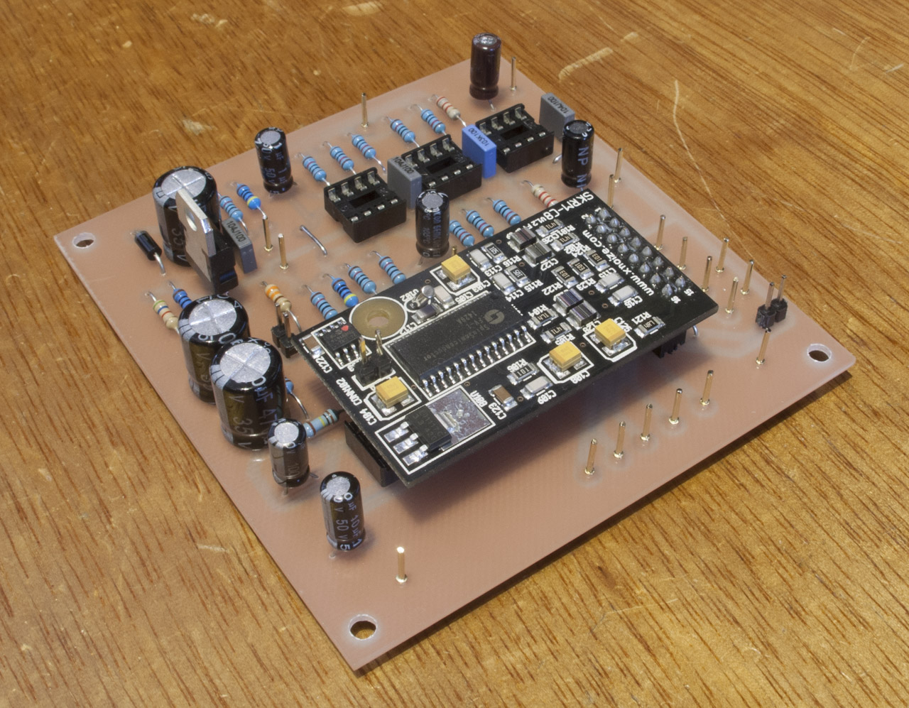
My latest "working" project is the UM-XN1 Digital Effects Unit. It uses the Spin Semiconductor's FN-1 DSP chip mounted and sold via Experimental Noize on an end user module. These modules come in 4 variations aimed at guitar effects processors.

My original plan for this unit was a guitar effects unit which emulates the distinct sound that Hank B Marvin from the 60's instrumental group, The Shadows, used with the help of multiple tape echo units. Some enthusiasts had worked their way through various tracks from The Shadows and also researched the tape echo units he used and created a set of patches utilizing the Experimental Noize module to recreate this vintage echo effects. The project for making a guitar effects unit can be found over at Echotapper

I purchased several of each of the different effects sets that Experimental Noize sells with the aim to also make effects modules for my analogue synthesizer setup. So in reality this first unit is a generic unit that uses line level signals whereas the guitar unit described above has a guitar preamp built into the effects unit.

The quality of the effects are quite high considering the affordability of the modules. They offer flanging, chorus, tremelo, stereo delays and echo, reverb. In reality the list is endless once you start to experiment with writing your own DSP code and uploading to the chip. Yes you can actually make your own effects. I became quite excited about this idea.

So the modules that Experimental Noize sell can essentially be plug into audio and power as they are though they do need controls added. These modules have connections for three potentiometers and also for a BCD switch which allows the selection of 8 programs. Connections to these modules are via a 16 pin connector which is aimed at being attached to another printed circuit board as I have done.


The Experimental Noize module is the small daughter board containing the multi-pin chip. This chip is the FV-1 produced by Spin Semiconductor. Have a good look around their site to see what you can do with this chip along with a forum with very useful information and new patches for the chip. I've also added some audio buffering as described in the documentation which comes with the EN modules. The board also contains a dc regulator circuit which supplies the needed 0-4.5-9v supply. I'm using a 12v dc plugpack.

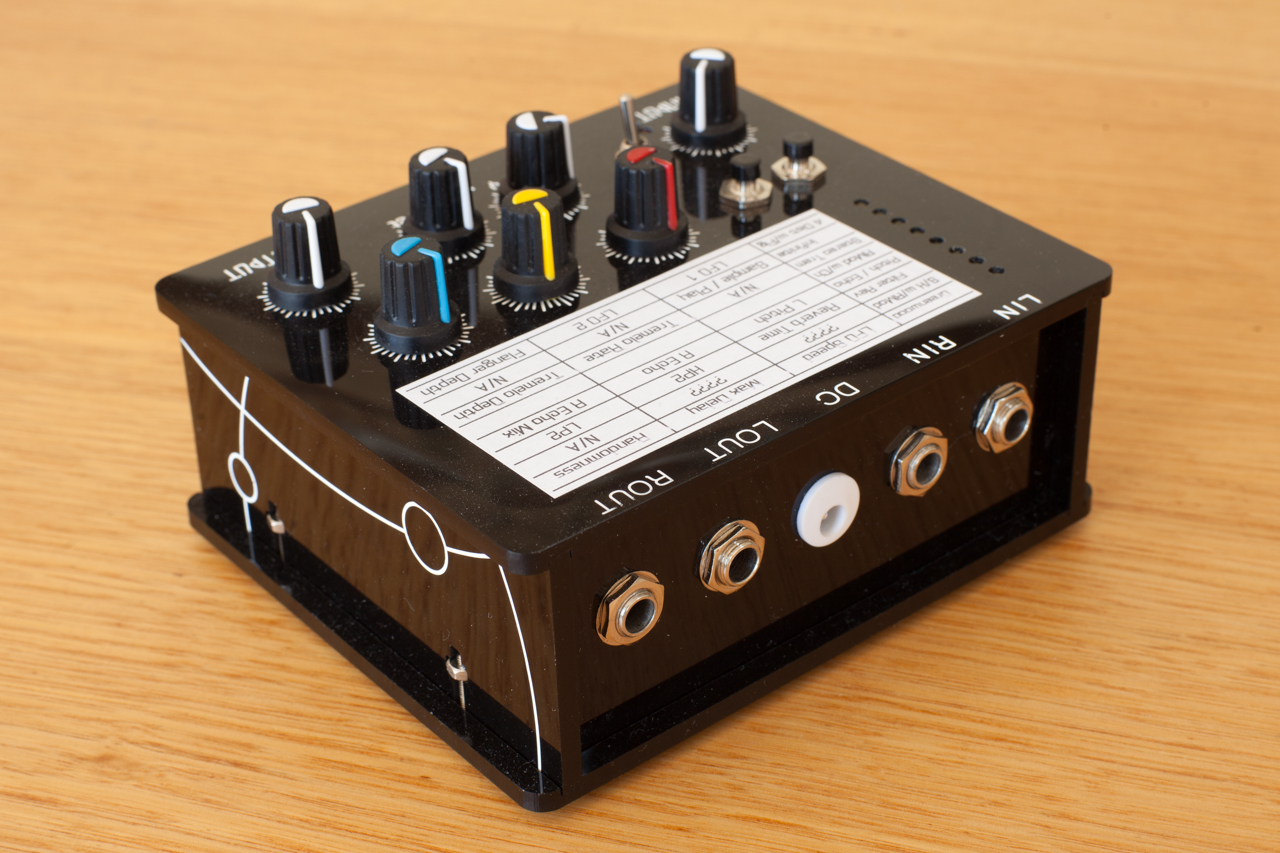
The UM-XN1 has stereo input and stereo outputs. One of the small issues with the preprogrammed modules is that some are mono in and out and others are mono in and stereo out. These limitations are not the hardware but the programs that are loaded into these modules. They are aimed at mono applications like guitar amplifiers. It was due to this that I put in a switch on my unit which allows for the stereo input to be summed to a mono signal so that the effects processor gets all the input signal.

My design contains an Input and Output Level controls along with a Dry and Wet signal level controls. As I was planning on experimenting with effects that users on the forum had created, there was no promise that some of them wouldn't be stereo. Although once I learn how I am sure I can modify the code to make all effects work in a stereo image.


I had to make a decision on how to control the BCD switch arrangement. The module has 3 inputs for the switch connector which allows for the selection of 8 programs. These switch inputs are a binary representation of the program number. I found several circuits that would allow a standard wafer switch to control these programs but I decided that I wanted an interface where I could have leds showing which program is currently selected. I decided on using an Arduino Nano to read the two momentary push buttons which are Program Up and Down. It also lights 8 leds which are arranged next to the program name and parameter list and of course it outputs the binary code to control the effects module. The program name and parameter list on this unit is an adhesive print which allows me to change the patches and reprint a label.

The Echotapper project(s) detail a unit which takes another step further whereby an Arduino is used to control the parameter values as well allowing for a recallable patch system with LCD display. This is also my plan for further units.

I am very happy with the results of this first unit. The photo of the board above looks quite neat although there were a couple of mistakes on my schematic and I also added the Dry and Wet mix controls after I had made this design.

The case is something that I start with the UM-SLM unit. It is a good design for minimising the use of nuts and bolts with your custom designed and CNC routed cases. Due to the placement of these case bolts there is bolts intruding inside the case. The sides and top are glued together the clever design on the two sides hold the nuts in places for the four base bolts. It can be a little fiddly putting the case back together as the nuts are not held in place when the bolt is not connected. So you have to be careful not to let the last one you tighten to fall inside the case. I could possibly work out a way of stopping this but it isn't really a problem.

I think this unit may end up being the one that has the Hank B Marvin effects loaded onto it and I attach it via the effects loop on my Vox AC30.


UM20 - Studio Power Switcher 

This is a project that I've had in the background for several years. The basic function is to automatically control the power of several parts of my music studio with the idea of saving power.

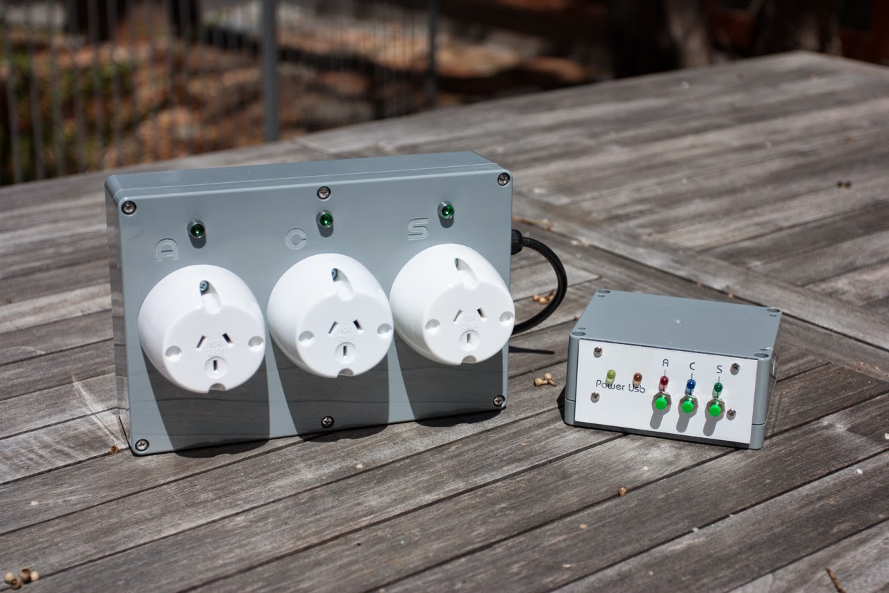
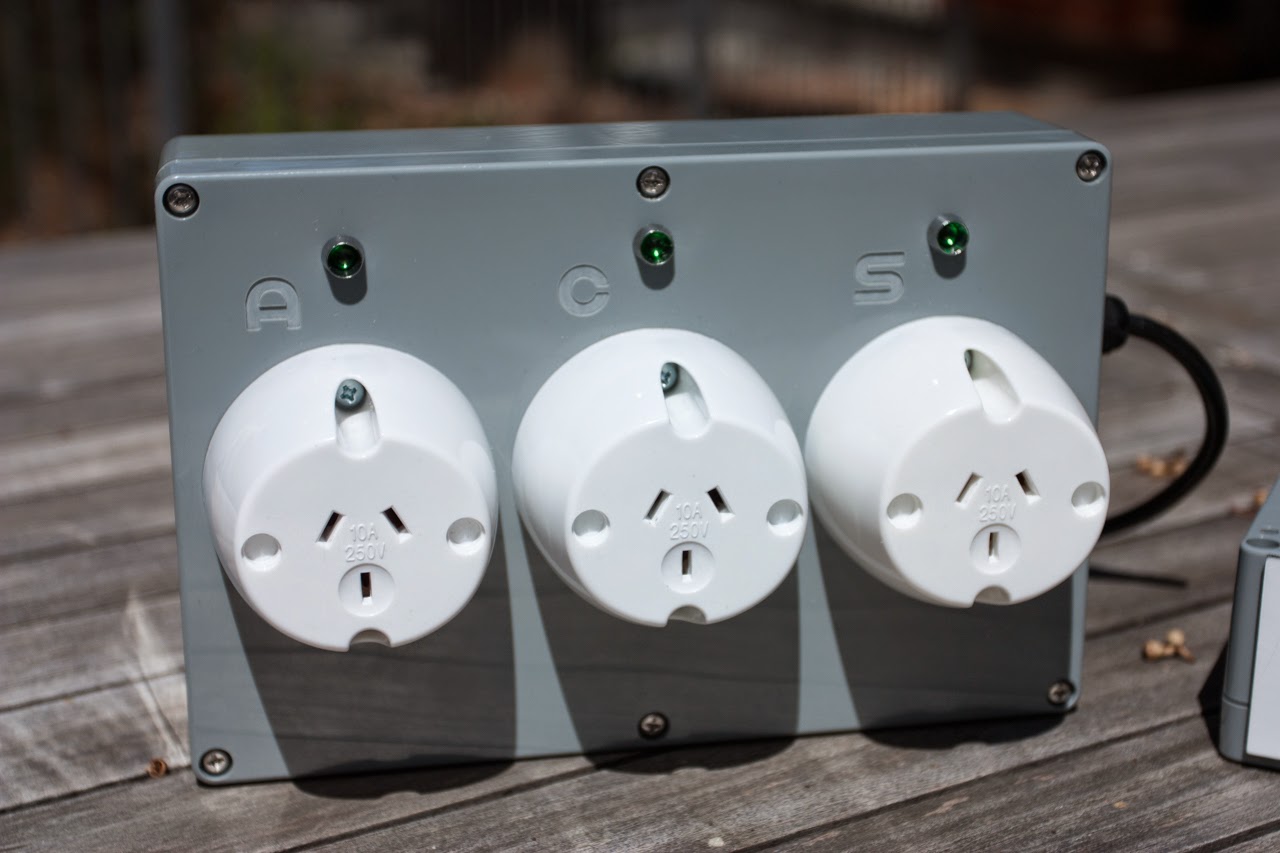
So there are three 240vac power circuits that are controlled within this unit. They are connected to the Computer circuit, the Speakers circuit and the Audio Circuit.

A small controller box contains the wonderful Arduino Nano microprocessor which controls the solid state relays which in turn power off and on the 240vac circuits. It also monitors the state of the audio sensor input and the firewire voltage coming from the PC.

The two automatic controls within this project are:
  1. When there has been no audio fed to the Speakers for a pre determined period of time then they will be automatically powered down. They will power up again once audio is detected.
  2. Once the IBM-PC powers down, all the 240vac outputs will also be turned off and after a preset period of time.
The Arduino gets a feed from the PC which is the power from the Firewire connection. On this particular computer motherboard it turns off the 12vdc feed along the firewire when the computer is shutdown. So the Arduino monitors this 12vdc state via one of it's digital inputs.

To sensor the presence of an audio signal I made up a small audio buffer circuit which I installed within my UM1-UK mixer which sums the left and right channels and outputs a voltage just below 5v which can be read in via the Arduino's analog inputs.

So the main purpose of this unit is to save power. My daily backup starts at about 4pm which is often about an hour before I finish using it. But what is unpredictable is how long this backup will take as its time will be based on how data needs copying to the backup hard drive. On several occasions I have forgotten to return to the studio to turn off the power especially to the Speakers which use a good 200W when idle. I also will forget to turn off my synthesizer which are growing in number and also power consumption.

So once the unit is fully installed I can stop worrying about whether I've turned the system off or not as this UM20 unit will take care of operation for me.

Both parts of the UM20 Studio Power Switcher


Closeup of the 240vac relay box

Closeup of the Computer Control box


As you can see on this controller box there are several leds which simply light to show the state of the labelled relays or incoming signals. The S (speaker) led will flash when there is no signal monitored on the audio sensor input. If you hold either the A (Audio) or S (Speakers) button down for 2 seconds then they will turn off.

I've written the code to take into a few unwelcome situations. For example you don't want to be able to turn off the computer circuit from this box when there is a power signal being read on the firewire cable. Note that it does say USB on the front panel as originally I had planned to use the USB port as a computer state signal but alas I forgot to change the panel artwork when I realised the USB still had power once the computer was powered down.

The unit has always got power from a small plugpack (wallwart) that supplies the 5vdc to power the Arduino and leds.

If anyone would like circuit diagrams then I'm quite happy to put this on the pages.

Therematron - The Base Panel 

The CNC Router that I purchased earlier in the year was to cover several purposes - create printed circuit boards, cut wood for cases and the like and also to cut front panels for projects.

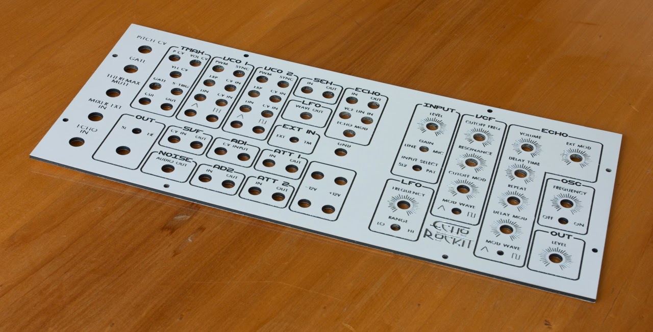
There has been quite a bit of trial and error with the front panels. The material I use is a composite material that has several brand names - Signbond, Dibond to name a couple. As I've mentioned before it is a material the comes in several different thicknesses but I use the 3mm thick model. It is comprised on 0.3mm layer of aluminium, 2.4mm of pvc and another 0.3mm layer of aluminium.

So far I have used a few different cutting bits for the CNC router. When I got the CNC I first tried a 0.2mm engraving bit which I still partly use, I've tried a 0.2mm end mill to no avail - it is not strong enough to cut through the aluminium and I've also used 0.5mm end mills and 1mm end mills.

My issue was that I wanted to cut lines into the signbond that we less than 0.5mm wide which often worked with the 0.2mm engraver but I found that I soon blunted these engravers. So I have now come up with a reasonable but slow process. I firstly cut the lines to a depth of 0.2mm with the 0.2mm emgraver then I recut the lines with the 0.5mm endmill to a depth of 0.4mm. This works quite well and the resulted board was done with this method.

But why don't you just use the 0.5mm endmill you ask ? Well the issue with this bit is that the shaft of 0.5mm is not strong enough to cut a straight line. The bit moves around once the initial pressure has been applied and bit cuts through that 0.3mm of aluminium. This is why I use the 0.2mm engraver first because it partially cuts into the aluminium but more importantly it creates a track for the 0.5mm endmill to follow.

Mind you this process takes quite a while. The resulting board took about 12 hours to cut. I did this is several goes. I did the fine lines in one cutting session which took most of this time and then the 1mm end mill was used to cut the thicker lines and also to cut out the holes in the board.


The board ends up in quite a mess once the cutting has been done. I firstly vacuum off as much sworf as possible and then I sand off the panel with a sanding block. This manages to clean up any of the cuts that are a little messy. I vacuum again and then cleanup any of the cuts with a small knife. Once this is done I give the board a good clean with a light abrasive cleaner like Jif. This does a good job of cleaning the white board. Give the whole board a rinse under water and let it dry. The final process that I did on this board was to give it a few coats of clear sealant. I used a art based spray which is meant for sealing art works but it seems reasonably strong and flexible. I've not looked into something strong and more durable as I have the clear spray in my cupboard.

So the next step is to do the large Top panel. I've looked at some of the settings for the router and found that I can hasten the cut by changing a few values during the movements.

What I have learnt from this design is that I should aim to have larger text and larger lines which means making the whole design less compact. Although I've managed to cut this panel and I am happy with the final product, the time it tool to produce this final panel was about a week.

Any questions, please ask. Stay tuned for the Top Panel and then comes the wiring stage !!!

Therematron - The Case 

At last I have almost completed the case for the Therematron. The process of creating this case was a test case for using the CNC router to make all the pieces of a wooden case which will have no nails or screws and is held together with glue. I wanted a process where I did not have to handle the wood apart from holding it down for cutting to pulling up the final piece. This was a trial of patiences.

Having purchased the 3040 CNC Router from BilbyCNC here in Australia I wanted to use its abilities to the maximum. I had initially purchased the unit to create front panels and printed circuit boards. I've perfected the creation of single sided printed circuit boards with a total of 9 boards now created with one of them being about A4 in size. But to extend the use of the router I thought about using it to create wooden cases.

I designed up the case in SketchUp which I've previously posted. Due to the limiting nature of the free version of SketchUp I returned to using Freehand to design the panels for the case so I would have two dimension pieces. Not ideal. So each panel was designed in Freehand but one of the disadvantages of using a 2d vector package is that it is not 3d and what I was creating was several 3d pieces of wood. 

So initially when cutting the pieces of wood I would need to cnc route one side and then flip this piece of wood over to cut away excess wood to make the tongue part of the joint. The problem was that my alignment was not accurate enough. I needed to be half a millimetre accurate for all these snug joints to work. I cut a whole case before I realised there was to much error in my work.

A rethink was needed. I had to make the pieces of box with only single sided cuts. So this is where I decided that instead of making the the piece with tongues out of one piece of wood, I would cut  grooves into the wood and use pieces of mdf a bit like dowels. I was a little worried that this method would not have enough strength to hold the box together but it has. What has possibly helped to strengthen the case is the several pieces of square aluminium tubing which will be the mounting points for the front panel.

Therematron Case without front and rear panels
The picture above is the current state of the case. Its constructed of marine ply because I happened to have some left overs in the shed. You can also see the aluminium bars where the front panel will mount. The side pieces of aluminium are angled so they are mounted to the side pieces of wood and can then also be mounted to the front panels. The nice thing about creating all the holes on the CNC router is their accuracy. So I can easily cut an angled section out for the square tubing and have it perfectly line up with the opposite side panel. For me to do this without and computer controlled router would be beyond my patiences.

Here are the diagrams out of Freehand for one of the side panels. The other panel is just mirrored.

The outside of the left panel

The atomic symbol on the side is just a retro nod to the Interociter of This Island Earth fame.

The inside of the Left Side Panel
So what is shown here is the inside of the left panel. The red outline is the outline cut of the wood. The green areas are 8mm deep routed pocket cuts and the yellow areas are 2mm deep pocket cuts. The reason the square cuts have discs in their corners is so the rounded 3.175mm end mill cutter can give me square corners for the aluminium tubing. Note that I made these discs a little larger than they needed to be so that the 3.175mm cutter cuts the line in one run instead of raising the Z axis and cutting the discs separately. This is something you learn to do with a router so that the cuts are more efficient. The yellow pockets are where the angle aluminium sits and is countersunk to 2mm so once the 2mm thick aluminium is mounted it is flush to the wood.

The holes to mount the tubing and angle aluminium are 0.5mm larger than their mate so the mating is not overly tight.

Shows the aluminium having been mounted
(note that the angle pieces are little short which is
just because that's what I had in the shed)
The front, base and top pieces of wood are simpler as they only need to join to the sides and don't have any special parts.

The case clamped together
It was quite a challenge to put glue in all the joints and place all the aluminium in at the same time.
Here you can see the MDF dowels on the base
So I've learnt that it can be done. And when I make my next case I will be able to knock one up in a day or so.

The next stage of the Therematron is to cut the front panels. This is also a new stage. I initially had reasonable success with using 0.2mm engraving bits with signbond composite panel but found that I quickly blunted them so I will trial using 0.5mm endmill bits very soon. Stay tuned.